background image

29

7200790 Service Manual for the HELION

®

 XENION

®

 Surgical Lighting System GB

10 Testing the Electrics of the Support System

10.3

10.3

10.3

10.3

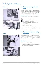
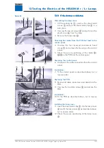
10.3 Dismantling the light head

Dismantling the light head

Dismantling the light head

Dismantling the light head

Dismantling the light head

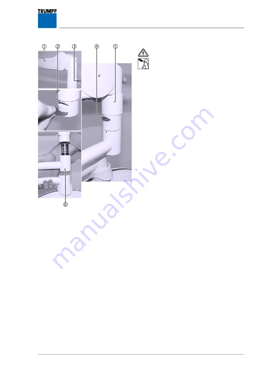
WARNING - Sudden release of spring arm:

• The spring arm 

1

 is under high tension. If

the lamp 

6

 is not removed in the upper-

most spring arm position, the spring arm

1

 releases suddenly, springing upwards,

and can cause serious injury.

• Only dismantle the lamps 

6

 when the sp-

ring arm 

1

 is in the uppermost position.

1. Place the spring arm 

1

 (in the example: Acrobat

2000) in the uppermost position.

2. Unscrew the cross-recessed head screw 

3

 and

push the sleeve 

5

 up.

3. Using a small screwdriver, remove the locking seg-

ment 

4

 from the slot 

2

 and put it in a safe pla-

ce.

4. Remove the light head 

6

 with cardanic suspensi-

on from the spring arm 

1

 and carefully put it

aside.

10.4

10.4

10.4

10.4

10.4 TTTTTesting the cables in the spring arm

esting the cables in the spring arm

esting the cables in the spring arm

esting the cables in the spring arm

esting the cables in the spring arm

that lead to the contact block in the ex

that lead to the contact block in the ex

that lead to the contact block in the ex

that lead to the contact block in the ex

that lead to the contact block in the ex-----

tension arm

tension arm

tension arm

tension arm

tension arm

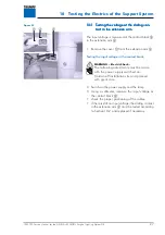
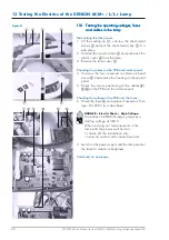
1. Carry out an all-pole contact resistance test bet-

ween the spring arm (sliding coupling) and the
contact block in the extension arm:

If the resistance is infinite, the spring arm must be
replaced in accordance with Section 10.5.

• If the resistance is almost zero, the cables in the

light head and the cardanic suspension must be
tested:

-

Carry out a contact resistance test between the
input terminal of the electronics and the sliding
connector on the cardanic suspension (replace
entire cabled cardanic suspension if necessary).

Figure 03

Содержание HELION L

Страница 1: ...XENION HELION Surgical Lighting System Service Manual...

Страница 2: ...g system with the following variants 1 to 4 fold suspension with the following types of lamp HELION with halogen lamp HELION S HELION M M HELION L L XENION with metal vapour lamp XENION M M XENION L L...

Страница 3: ...r in associa tion with the use of said information prohibited in this manner by any person or company TRUMPF KREUZER Medizin Systeme GmbH Co KG reserves the right to amend delete or modify in any othe...

Страница 4: ...ng the L Changing the L Changing the Lamp amp amp amp amp 17 17 17 17 17 5 1 Changing the lamp of the HELION S 17 5 2 Changing the lamp of the HELION M M L L 17 5 3 Changing the lamp of the XENION M M...

Страница 5: ...cus unit 33 11 2 Testing the voltages and cables in the lamp 34 12 12 12 12 12 T T T T Testing the Electrics of the esting the Electrics of the esting the Electrics of the esting the Electrics of the...

Страница 6: ...ON M M HELION L L HELION XL XENION M M XENION L L lamps 59 15 2 9 7 pole plug cardanic suspension TruVidia 8 pole DIN socket 60 15 2 10 5 pole plug TFT LCD monitor with cardanic suspen sion optional D...

Страница 7: ...th TruVidia 80 15 2 30 XENION M light head 81 15 2 31 XENION M light head with wall control panel 82 15 2 32 XENION M light head with fixed focus camera 83 15 2 33 XENION M light head with TruVidia 84...

Страница 8: ...mmediately con tact your nearest TRUMPF KREUZER Customer Service Centre for your own safety and that of the hospital staff and patients Only carry out repairs that you are familiar with from your trai...

Страница 9: ...4 W W W W Warranty and liability arranty and liability arranty and liability arranty and liability arranty and liability TRUMPF KREUZER Medizin Systeme GmbH Co KG assumes no liability for the reliabl...

Страница 10: ...severe or even fatal injury Failure to comply may result in severe or even fatal injury Failure to comply may result in minor or moderate injury or damage to property Offers tips on usage and handy in...

Страница 11: ...ystem parts alling lighting system parts alling lighting system parts alling lighting system parts alling lighting system parts DANGER Falling lighting system parts During servicing it is not permitte...

Страница 12: ...p Always change both lamps When replacing the lamp always re place the entire lamp unit In the case of HELIUM models the lamp base must also be repla ced Damage to components of the lighting system Da...

Страница 13: ...d clothing Only work in the operating theatre with the permission of the user Observe the code of practice in force at the medical facility particularly in the operating theatre If you have any sympto...

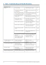
Страница 14: ...of lamp cardanic suspension spring arm or extension arm 10 Defective sliding contact in extension arm Replace sliding contact in extension arm check slip ring on central column 10 1 10 2 Defective ca...

Страница 15: ...fuse on PCB defective Check positioning of cables on PCB and control panel replace PCB replace fuse replace cables in light head 12 2 Line contact on PCB in light head defective PCB defective fuse on...

Страница 16: ...k replace internal electrical supply line in extension arm 10 6 10 7 Defective slip ring on central column Replace slip ring on central column 10 8 10 9 Contact areas burnt damaged Check operating vol...

Страница 17: ...e HELION M Changing the lamp of the HELION M Changing the lamp of the HELION M Changing the lamp of the HELION M M L L M L L M L L M L L M L L The display 8 is lit up The lamp is defective Removal 1 U...

Страница 18: ...grip 2 by means of the unlocking device 1 and remove it 2 Undo the three screws 3 and remove the focus unit 5 3 Remove the old metal vapour lamp 4 by pulling it upwards and dispose of it in an appropr...

Страница 19: ...amp Always change both lamps supplied as a set 4 Using a screwdriver push out the old halogen lamp 4 remove it from the aperture attachment 5 and dispose of it in an appropriate manner 5 Remove the ol...

Страница 20: ...ead screw 7 in a short way Installation 4 Fit the components as described above but in the reverse order WARNING Electric Shock The following adjustments must be made with the power supply switched on...

Страница 21: ...ead screw 9 in a short way Setting WARNING Electric Shock The following test must be carried out with the power supply switched on Cordon off installation site and proceed with great care 4 Switch on...

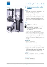
Страница 22: ...ocking varnish Installation 7 Fit the components as described above but in reverse order 6 4 6 4 6 4 6 4 6 4 Setting the luminous field for the XENI Setting the luminous field for the XENI Setting the...

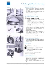
Страница 23: ...ench and unscrew the four countersunk Al len screws 8 5 Remove the plastic ring 7 6 Lift the filter glass assembly A and SUB D con nector HEL high voltage contact plug XEN B carefully up and out of th...

Страница 24: ...n If the remaining lamp 5 is not in the centre check if the position of the cables 6 is preventing the lamp 5 from swivelling change the polarity of the servomotor Changing the polarity 7 Lift the sea...

Страница 25: ...o lamps 5 onto the middle axis rep resented by the dashed line Fitting the focus unit 4 Insert the focus unit 4 into the lamp so that both the plug connectors 7 are aligned then activate the lamp Func...

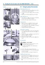
Страница 26: ...witched on Cordon off installation site and proceed with great care 2 Switch on the power supply 3 Using a voltmeter measure the input voltage at the transformer terminal 1 If there is no input voltag...

Страница 27: ...t in the extension arm The input voltage is measured at the contact block 3 in the extension arm 2 1 Remove the cover 1 from the extension arm 2 Testing the input voltage at the contact block WARNING...

Страница 28: ...arm 2 NOTE in the case of 7 pole sliding contacts Disconnect the low voltage plug connection 3 2 Unscrew the two socket head cap screws size 5 4 and put them in a safe place 3 Disconnect the cables a...

Страница 29: ...c suspensi on from the spring arm 1 and carefully put it aside 10 4 10 4 10 4 10 4 10 4 T T T T Testing the cables in the spring arm esting the cables in the spring arm esting the cables in the spring...

Страница 30: ...g in connector 4 from the spring arm 5 6 Carefully put the spring arm 5 aside 10 6 10 6 10 6 10 6 10 6 T T T T Testing the cables in the extension arm esting the cables in the extension arm esting the...

Страница 31: ...sconnect the cables at the terminal block 6 and remove the sliding contact 7 4 Provide the cables 4 with a wire pull and pull them through the extension arm 2 Installation 5 Install the new cables 4 w...

Страница 32: ...ctrical cables of the slip ring 8 concerned 7 Unscrew the cross recessed head screw 6 on the slip ring 8 8 Remove the slip ring 8 from the central column by feeding the electrical cables 7 into the ce...

Страница 33: ...ocus unit 5 Preparing for measurement 3 Place three test prods 4 on the contacts of the focus unit 5 4 Insert the focus unit 5 Carrying out measurement WARNING Electric Shock The following adjustments...

Страница 34: ...trol panel 4 Check the secure positioning of the cables 7 8 on the PCB and the control panel Checking the voltages at the PCB WARNING Electric Shock The following measurements must be made with the po...

Страница 35: ...oceed with great care 8 Switch on the power supply and the lamp and if necessary set the lamp to maximum brightness Measure the voltage at the contacts of the filter glass assembly 9 Using a voltmeter...

Страница 36: ...focus unit 5 Prepare for measurement 3 Place three test prods 4 on the contacts of the focus unit 5 4 Insert the focus unit 5 Carry out measurement WARNING Electric Shock The following adjustments mu...

Страница 37: ...screws 7 and remove the housing on the control panel 5 Check the secure positioning of the cables 8 C D on the PCB and the control panel Checking the fuse and the voltage at the PCB 6 Check the fuse A...

Страница 38: ...nd proceed with great care 9 Switch on the power supply and the lamp and if necessary set the lamp to maximum brightness Measure the voltage at the contacts of the filter glass assembly 10 Using a vol...

Страница 39: ...to the control panel 4 Unscrew the four recessed countersunk head screws 7 and remove the housing on the control panel 5 Check the secure positioning of the cables 8 A Bon the PCB and the control pan...

Страница 40: ...two set screws 4 and push back the plastic cover 6 from the lamp 3 Remove the lamp cover 3 Checking the cables on the PCB and control panel 4 Unscrew the four recessed countersunk head screws 7 and r...

Страница 41: ...LED display D is lit up undervoltage Red LED display E is lit up overvoltage The voltage must be 24 V 0 5 V In the case of voltage deviations reset the volt age on the transformer in accordance with...

Страница 42: ...Unscrew the four recessed countersunk head screws 7 and remove the housing on the control panel 5 Check the secure positioning of the cables 8 9 on the PCB and the control panel Checking the cables fr...

Страница 43: ...ted in writing in accordance with the accept ance protocol and verified by the customer The equipment must be demonstrated to the customer on hand over 14 2 14 2 14 2 14 2 14 2 Inspection intervals an...

Страница 44: ...oints Checking the torques for heavy load anchors HELION S M types solo suspension heavy load anchor HSL M10 20 pull out torque Tinst 50 Nm is used for round ceiling anchor plates Types HELION XENION...

Страница 45: ...e ceiling tube have insulation rings 1 washers 2 and spring lock washers 3 Checking the ceiling tube bolt connection Check the secure grip of the fastening bolts 4 on the ceiling tube bolt connection...

Страница 46: ...conductor 5 and enter the measurement between this place and the main earthed conductor connection 2 in the test re port After assembly of the lamp or lamp combination measure the resistance between p...

Страница 47: ...nt Lubricate the projecting segment e g with Moly cote MOS 2 Checking the brake screws Check the adjustment of the brake screws in the extension arms and in the cardanic suspension If necessary tighte...

Страница 48: ...doing so read the operating instructions that correspond to the lamp type for the optional components e g monitor camera Checking the lamp changeover A HELION lamp versions With the unit switched off...

Страница 49: ...to 140 K Lux XENION L 145 to 160 K Lux HELION XL 125 to 145 K Lux Enter the values recorded in the test report Testing the lamp voltage at rated load Measure the lamp voltage at rated load Read the de...

Страница 50: ...XL L D 7201038 HELION XL S D 7201035 HELION XL M D 7201037 HELION XL M M D 7201053 Lamp designation Technical data sheets HELION S Ceiling D 7201001 HELION S Mobile 100 127 V D 7201002 HELION S Wall D...

Страница 51: ...HELION L M D 7201029 HELION L L M D 7201048 HELION L D 7201011 HELION L M D 7201028 HELION L L D 7201031 HELION L M D 7201027 HELION L L D 7201030 HELION L L L D 7201050 HELION L L L D 7201045 HELION...

Страница 52: ...ms and set values Circuit diagrams and set values Circuit diagrams and set values Circuit diagrams and set values Circuit diagrams and set values 15 2 1 HELION M M HELION L L HELION XL 15 2 1 HELION M...

Страница 53: ...rcuit diagrams and set values cont Circuit diagrams and set values cont Circuit diagrams and set values cont Circuit diagrams and set values cont Circuit diagrams and set values cont 15 2 2 XENION M M...

Страница 54: ...cal Lighting System GB 54 15 Technical Description 15 2 15 2 15 2 15 2 15 2 Circuit diagrams Circuit diagrams Circuit diagrams Circuit diagrams Circuit diagrams 15 2 3 15 2 3 15 2 3 15 2 3 15 2 3 XENI...

Страница 55: ...ng System GB 15 Technical Description 15 2 15 2 15 2 15 2 15 2 Circuit diagrams cont Circuit diagrams cont Circuit diagrams cont Circuit diagrams cont Circuit diagrams cont 15 2 4 15 2 4 15 2 4 15 2 4...

Страница 56: ...s and set values cont Circuit diagrams and set values cont Circuit diagrams and set values cont Circuit diagrams and set values cont 15 2 5 15 2 5 15 2 5 15 2 5 15 2 5 HELION M HELION L with wall cont...

Страница 57: ...values cont Circuit diagrams and set values cont Circuit diagrams and set values cont Circuit diagrams and set values cont 15 2 6 15 2 6 15 2 6 15 2 6 15 2 6 XENION M M XENION L L with wall control pa...

Страница 58: ...nd set values cont Circuit diagrams and set values cont 15 2 7 15 2 7 15 2 7 15 2 7 15 2 7 24 V supply A 24 V supply A 24 V supply A 24 V supply A 24 V supply AC DC HELION M M HELION L L HELION XL XEN...

Страница 59: ...and set values cont 15 2 8 15 2 8 15 2 8 15 2 8 15 2 8 Combination T Combination T Combination T Combination T Combination TruVidia with HELION M M HELION L L HELION XL XENION M M ruVidia with HELION...

Страница 60: ...et values cont Circuit diagrams and set values cont Circuit diagrams and set values cont 15 2 9 15 2 9 15 2 9 15 2 9 15 2 9 7 pole plug cardanic suspension 8 pole DIN socket T 7 pole plug cardanic sus...

Страница 61: ...set values cont Circuit diagrams and set values cont 15 2 10 5 pole plug cardanic suspension TFT LCD monitor optional DC DC converter 15 2 10 5 pole plug cardanic suspension TFT LCD monitor optional D...

Страница 62: ...15 2 15 2 Circuit diagrams and set values cont Circuit diagrams and set values cont Circuit diagrams and set values cont Circuit diagrams and set values cont Circuit diagrams and set values cont 15 2...

Страница 63: ...s cont Circuit diagrams and set values cont Circuit diagrams and set values cont Circuit diagrams and set values cont 15 2 12 TFT LCD monitor with monitor power supply unit 15 2 12 TFT LCD monitor wit...

Страница 64: ...rcuit diagrams and set values cont Circuit diagrams and set values cont Circuit diagrams and set values cont Circuit diagrams and set values cont 15 2 13 Plug connector T 15 2 13 Plug connector T 15 2...

Страница 65: ...cont Circuit diagrams and set values cont Circuit diagrams and set values cont Circuit diagrams and set values cont 15 2 14 Plug connector spring arms 3 pole 5 pole 7 pole 15 2 14 Plug connector sprin...

Страница 66: ...uit diagrams and set values cont Circuit diagrams and set values cont Circuit diagrams and set values cont Circuit diagrams and set values cont Circuit diagrams and set values cont 15 2 15 HELION M L...

Страница 67: ...lues cont Circuit diagrams and set values cont Circuit diagrams and set values cont Circuit diagrams and set values cont 15 2 16 HELION M L light head with fixed focus camera 15 2 16 HELION M L light...

Страница 68: ...uit diagrams and set values cont Circuit diagrams and set values cont Circuit diagrams and set values cont Circuit diagrams and set values cont 15 2 17 HELION M L light head with T 15 2 17 HELION M L...

Страница 69: ...uit diagrams and set values cont Circuit diagrams and set values cont Circuit diagrams and set values cont Circuit diagrams and set values cont Circuit diagrams and set values cont 15 2 18 HELION M L...

Страница 70: ...lues cont Circuit diagrams and set values cont Circuit diagrams and set values cont Circuit diagrams and set values cont 15 2 19 HELION M L light head with wall control panel 15 2 19 HELION M L light...

Страница 71: ...lues cont Circuit diagrams and set values cont Circuit diagrams and set values cont Circuit diagrams and set values cont 15 2 20 HELION M L light head with fixed focus camera 15 2 20 HELION M L light...

Страница 72: ...uit diagrams and set values cont Circuit diagrams and set values cont Circuit diagrams and set values cont Circuit diagrams and set values cont 15 2 21 HELION M L light head with T 15 2 21 HELION M L...

Страница 73: ...grams and set values cont Circuit diagrams and set values cont 15 2 22 HELION M L light head with fixed focus camera and wall control panel 15 2 22 HELION M L light head with fixed focus camera and wa...

Страница 74: ...Circuit diagrams and set values cont Circuit diagrams and set values cont Circuit diagrams and set values cont Circuit diagrams and set values cont Circuit diagrams and set values cont 15 2 23 XENION...

Страница 75: ...et values cont Circuit diagrams and set values cont Circuit diagrams and set values cont Circuit diagrams and set values cont 15 2 24 XENION M light head with wall control panel 15 2 24 XENION M light...

Страница 76: ...et values cont Circuit diagrams and set values cont Circuit diagrams and set values cont Circuit diagrams and set values cont 15 2 25 XENION M light head with fixed focus camera 15 2 25 XENION M light...

Страница 77: ...Circuit diagrams and set values cont Circuit diagrams and set values cont Circuit diagrams and set values cont Circuit diagrams and set values cont 15 2 26 XENION M light head with T 15 2 26 XENION M...

Страница 78: ...Circuit diagrams and set values cont Circuit diagrams and set values cont Circuit diagrams and set values cont Circuit diagrams and set values cont Circuit diagrams and set values cont 15 2 27 XENION...

Страница 79: ...et values cont Circuit diagrams and set values cont Circuit diagrams and set values cont Circuit diagrams and set values cont 15 2 28 XENION L light head with wall control panel 15 2 28 XENION L light...

Страница 80: ...Circuit diagrams and set values cont Circuit diagrams and set values cont Circuit diagrams and set values cont Circuit diagrams and set values cont 15 2 29 XENION L light head with T 15 2 29 XENION L...

Страница 81: ...Circuit diagrams and set values cont Circuit diagrams and set values cont Circuit diagrams and set values cont Circuit diagrams and set values cont Circuit diagrams and set values cont 15 2 30 XENION...

Страница 82: ...et values cont Circuit diagrams and set values cont Circuit diagrams and set values cont Circuit diagrams and set values cont 15 2 31 XENION M light head with wall control panel 15 2 31 XENION M light...

Страница 83: ...et values cont Circuit diagrams and set values cont Circuit diagrams and set values cont Circuit diagrams and set values cont 15 2 32 XENION M light head with fixed focus camera 15 2 32 XENION M light...

Страница 84: ...Circuit diagrams and set values cont Circuit diagrams and set values cont Circuit diagrams and set values cont Circuit diagrams and set values cont 15 2 33 XENION M light head with T 15 2 33 XENION M...

Страница 85: ...t diagrams and set values cont Circuit diagrams and set values cont 15 2 34 XENION M light head with fixed focus camera and wall control panel 15 2 34 XENION M light head with fixed focus camera and w...

Страница 86: ...Circuit diagrams and set values cont Circuit diagrams and set values cont Circuit diagrams and set values cont Circuit diagrams and set values cont Circuit diagrams and set values cont 15 2 35 XENION...

Страница 87: ...et values cont Circuit diagrams and set values cont Circuit diagrams and set values cont Circuit diagrams and set values cont 15 2 36 XENION L light head with wall control panel 15 2 36 XENION L light...

Страница 88: ...Circuit diagrams and set values cont Circuit diagrams and set values cont Circuit diagrams and set values cont Circuit diagrams and set values cont 15 2 37 XENION L light head with T 15 2 37 XENION L...

Страница 89: ...rcuit diagrams and set values cont Circuit diagrams and set values cont Circuit diagrams and set values cont Circuit diagrams and set values cont 15 2 38 HELION XENION transformer connector 15 2 38 HE...

Страница 90: ...oftware constr year version ser nr light intensity 1 2 3 4 pos input V AC input V DC Ri in Ohm V DC contactblock V DC Focus emergency switch over default value rem 1 n i O 2 n i O 3 n i O 4 n i O tech...

Страница 91: ...MODELLING residual illumination with tube and 2 shutters no stand req 41 41 Leneman laminar flow index 26 29 29 Oostlander laminar flow index 28 32 32 Electrical data HELION S HELION M HELION M Trans...

Страница 92: ...on with tube and 2 shutters 41 41 42 Leneman laminar flow index 28 28 93 Oostlander laminar flow index 32 32 119 Electrical data HELION L HELION L HELION XL Transformer mm L x W x H 120 x 103 x 118 12...

Страница 93: ...nation with tube and 2 shutters 41 41 Leneman laminar flow index 9 10 Oostlander laminar flow index 10 11 Electrical data XENION M XENION L Power supply unit mm L x W x H 199 x 110 x 50 125 5 x 125 2...

Страница 94: ...rd version The product has been tested and certified by the Testing and Certification Institute EU code no 0123 The marks licensing certificate entitles the device to bear the CE mark showing the numb...

Страница 95: ...95 7200790 Service Manual for the HELION XENION Surgical Lighting System GB Notes...

Страница 96: ...teme GmbH Co KG Benzstrasse 26 82178 Puchheim Germany Telephone 49 0 89 8 98 07 0 e mail info de trumpf med com Fax 49 0 89 8 09 07 20 www trumpf med com 7200791 Service Manual for the HELION XENION S...

Отзывы: