32
7200790 Service Manual for the HELION
®
XENION
®
Surgical Lighting System GB
10 Testing the Electrics of the Support System
10.9
10.9
10.9
10.9
10.9 RRRRReplacing the slip ring
eplacing the slip ring
eplacing the slip ring
eplacing the slip ring
eplacing the slip ring
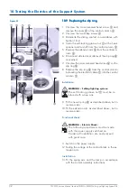
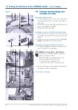
1. Unscrew the cross-recessed head screw
3
and
remove the cover
4
of the central column
5
.
2. Unscrew the two brake screws
2
.
3.
Dismantle the sliding contact in accordance with
Section 10.2.
4. Undo the self-locking groove nut
1
with a hook
spanner and twist off from the central column
5
.
5. Remove the extension arm
9
from the central co-
lumn
5
.
6. Disconnect all electrical cables of the slip ring
8
concerned.
7. Unscrew the cross-recessed head screw
6
on the
slip ring
8
.
8. Remove the slip ring
8
from the central column
by feeding the electrical cables
7
into the central
column
5
.
Installation:
WARNING – Falling lighting system:
The self-locking groove nut
1
must be re-
placed with a new one.
9. Fit the new slip ring
8
as described above, but in
reverse order.
10.Fit the extension arm as described above, but in
reverse order.
Functional check:
WARNING – Electric Shock:
The following adjustments must be made
with the power supply switched on.
Cordon off installation site and proceed
with great care.
11.Switch on the power supply.
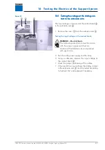
12.Testing the voltage at the contact block in the ex-
tension arm.
Installation:
13.Fit the spring arm and the lamp in accordance
with the current assembly instructions.
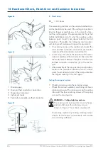
Figure 07


