28
7200790 Service Manual for the HELION
®
XENION
®
Surgical Lighting System GB
10 Testing the Electrics of the Support System
10.2
10.2
10.2
10.2
10.2 RRRRReplacing the sliding contact in the ex
eplacing the sliding contact in the ex
eplacing the sliding contact in the ex
eplacing the sliding contact in the ex
eplacing the sliding contact in the ex-----
tension arm/testing the slip ring on the
tension arm/testing the slip ring on the
tension arm/testing the slip ring on the
tension arm/testing the slip ring on the
tension arm/testing the slip ring on the
central column
central column
central column
central column
central column
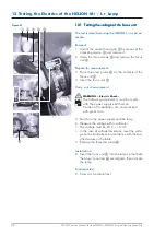
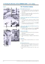
Removal:
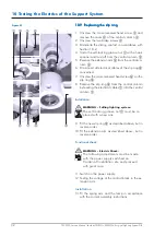
1. Remove the cover
1
from the extension arm
2
.
NOTE – in the case of 7-pole sliding contacts:
Disconnect the low-voltage plug connection
3
.
2. Unscrew the two socket head cap screws size 5
4
and put them in a safe place.
3. Disconnect the cables at the terminal block
5
and remove the sliding contact
6
.
Testing the slip ring on the central column:
4. Before fitting a new sliding contact
6
check that
the slip ring on the central column is functioning
properly:
5. Carry out a contact resistance test between the
terminal block on the transformer and the slip ring
in the extension arm:
• If the resistance is infinite, the slip ring must be
replaced in accordance with the following sec-
tions:
- 10.3 Dismantling the light head,
- 10.5 Dismantling the spring arm,
- 10.8 Dismantling the central column,
- 10.9 Changing the slip ring.
Installation:
5. Fit the new sliding contact
6
as described above,
but in reverse order.
6. Fit the cover
1
.
Figure 02

