31
7200790 Service Manual for the HELION
®
XENION
®
Surgical Lighting System GB
10 Testing the Electrics of the Support System
10.7
10.7
10.7
10.7
10.7 RRRRReplacing the cables in the extension
eplacing the cables in the extension
eplacing the cables in the extension
eplacing the cables in the extension
eplacing the cables in the extension
arm
arm
arm
arm
arm
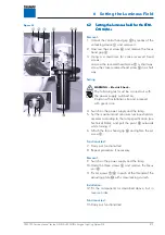
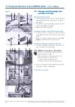
After the lamp and the spring arm have been disman-
tled, the cables in the extension arm can be replaced.
Removal:
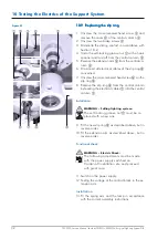
1. Remove the cover
1
from the extension arm
2
.
NOTE – in the case of 7-pole sliding contacts:
Disconnect the low-voltage plug connection
3
.
2. Unscrew the two socket head cap screws size 5
5
and put them in a safe place.
3. Disconnect the cables at the terminal block
6
and remove the sliding contact
7
.
4. Provide the cables
4
with a wire pull and pull
them through the extension arm
2
.
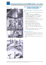
Installation:
5. Install the new cables
4
with pre-assembled slid-
ing connector as described above, but in reverse
order.
6. Fit the spring arm and the lamp in accordance
with the current assembly instructions.
7. Carry out functional test.
10.8
10.8
10.8
10.8
10.8 Dismantling the central column
Dismantling the central column
Dismantling the central column
Dismantling the central column
Dismantling the central column
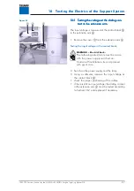
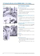
WARNING – Heavy weight:
Two people are needed to dismantle a cen-
tral column with 2 - 4 extension arms.
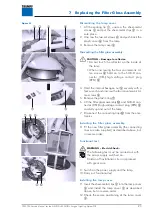
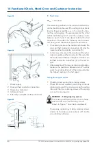
1. Unscrew the six recessed countersunk head screws
M8 x 15 mm
4
.
2. Carefully remove the central column
1
from the
ceiling tube
2
.
3. Undo the plug connections
3
and carefully lay
down the central column
1
.
Figure 05
Figure 06


