VGA2 Connector
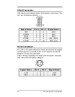
INT_VGA is for internal Video A/D board connection. The
pin out is listed as below:
Signal Name
Pin # Pin # Signal Name
RED
1
2
GND
GREEN
3
4
GND
BLUE
5
6
GND
HSYNC
7
8
DDC_DATA
VSYNC
9
10
DDC_CLK
DCIN Connector
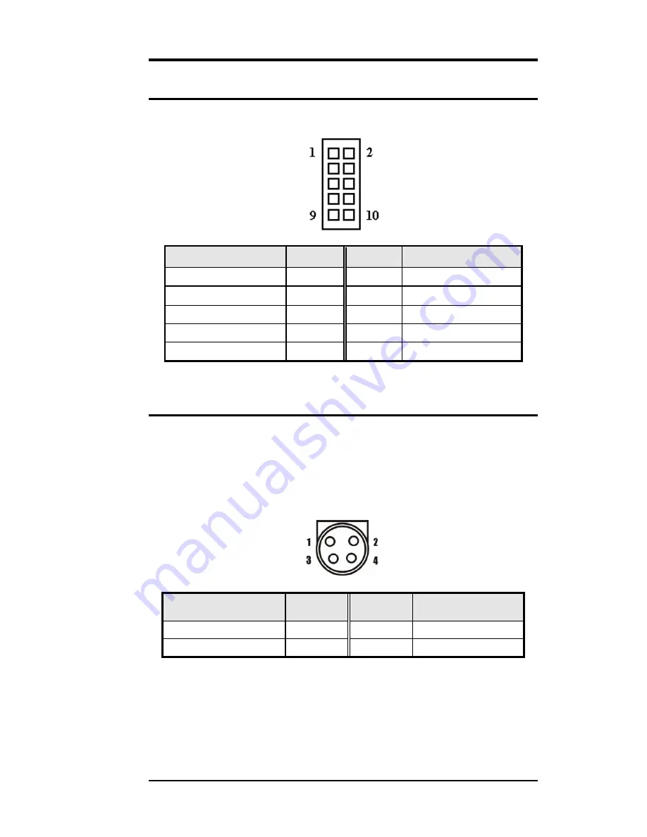
DC_IN1 is for external power input connection to supply
system power. It needs to be +12V input from AC/DC
adapter within 5% tolerance.
Users should calculate the total system power required
and use sufficient rating adapter.
Signal Name
Pin #
Pin # Signal Name
+12V
1
2
+12V
GND
3
4
GND
30
TR-LCD1900-ITX-7 User Manual
Содержание TR-LCD1900-ITX-7
Страница 17: ...Jumper Locations on the TR LCD1900 ITX 7 16 TR LCD1900 ITX 7 User Manual ...
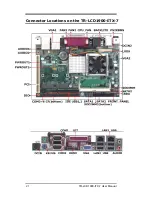
Страница 22: ...Connector Locations on the TR LCD1900 ITX 7 21 TR LCD1900 ITX 7 User Manual ...
Страница 46: ... Exit Without Saving Abandon all CMOS value changes and exit setup 45 TR LCD1900 ITX 7 User Manual ...
Страница 96: ......
Страница 97: ......
Страница 98: ......
Страница 99: ......
Страница 100: ......
Страница 101: ......
Страница 102: ......
Страница 103: ......
Страница 104: ......
Страница 105: ......
Страница 106: ......
Страница 107: ......


