


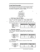


Front Panel Connector
The front panel of the case has a control panel, which
provides light indication of the computer activities and
switches to change the computer status.
ATX Power ON/OFF Button
This 2-pin connector acts as the “Power Supply On/Off
Switch” on the
TR-LCD1
9
00-ITX-
7
main board. When
pressed the,
switch will force the Main board to power on.
When
pressed again, it will force the main board to power off.
PWR BTN Pin # Signal Name
1
PWR-BTN
6
GND
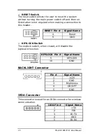
HDD LED Connector
This connector connects to the hard drive activity LED on
control panel. This LED will flash when the HDD is being
accessed.
HDD LED Pin # Signal Name
2
VCC
7
HDDLED
Power-On LED
This connector allows users to connect to Front Panel
Power indicator.
Power-On Pin # Signal Name
3
VCC
8
GND
22
TR-LCD1900-ITX-7 User Manual
Содержание TR-LCD1900-ITX-7
Страница 17: ...Jumper Locations on the TR LCD1900 ITX 7 16 TR LCD1900 ITX 7 User Manual ...
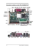
Страница 22: ...Connector Locations on the TR LCD1900 ITX 7 21 TR LCD1900 ITX 7 User Manual ...
Страница 46: ... Exit Without Saving Abandon all CMOS value changes and exit setup 45 TR LCD1900 ITX 7 User Manual ...
Страница 96: ......
Страница 97: ......
Страница 98: ......
Страница 99: ......
Страница 100: ......
Страница 101: ......
Страница 102: ......
Страница 103: ......
Страница 104: ......
Страница 105: ......
Страница 106: ......
Страница 107: ......


