background image

Resistive 

Touchscreen

 Option

USB Controller Driver Installation

All Windows drivers are included on the Transduction 

TR-

LCD1

9

00-ITX

-

7


5

-wire 

Touchscreen Drivers CD along with Troubleshooting.

NOTE: For Win XP and 2000 you MUST logon with administrator’s password.

TouchKit

 software on the driver CD has the required drivers and the utility for toggling 

between left and right mouse buttons and configuration support. These will all be installed 

when Setup.exe is run from the CD.

For Windows 2000/XP

/Windows 7

When the New Hardware Found message comes up, choose 

Cancel

. Run the 

Setup.exe


program from 

t

he driver CD.

Please note that the touch screen controller in the TR-

LCD1

9

00-ITX

-

7

 is 

USB

 and follow 

the prompts accordingly.

Windows will copy the files to your hard drive and setup will be complete. (Windows XP will 

give a warning message about the TouchKit Controller certification, press 

Continue

 anyway.)

Please reboot your computer.

Windows will now find the device automatically and it will be listed in the Device Manager as:

TouchKit USB Controller.

TouchKit Software

There are five property pages:

1. 

GENERAL

: Language selection, add/remove devices, 4-point Calibration, Draw Test and 

Advanced

4 pts Cal

Choose to calibrate your screen by touching the blinking symbol on the panel until you 

get a beep or it stops blinking

Draw Test

Test the drawing position in relation to the display screen to verify panel linearity, 

calibration capability and drawing line quality.

NOTE: 

Download USB Touch Screen Driver For Windows 2K/XP

/7

8

8

TR-LCD1

9

00-ITX-

7

 User Manual

Содержание TR-LCD1900-ITX-7

Страница 1: ... 26 15 TR LCD1900 ITX 7 INDUSTRIAL PANEL RACK MOUNT PC WITH INTEL DUAL ATOM PROCESSOR AND 19 LCD TOUCH SCREEN DISPLAY 5155 Spectrum Way Mississauga ON Canada L4W 5A1 TEL 1 800 268 0427 905 625 1907 FAX 905 625 0531 Email sales transduction com ...

Страница 2: ... LCD1900 ITX 7 SBC 15 Jumper Locations on the TR LCD1900 ITX 7 SBC 16 JP1 JP2 COM Power Selection 17 JP3 Clear CMOS RAM Data 17 JP4 CF Card Mode Selection 18 JP5 COM1 Power Pin Pin9 18 AT MODE AT Mode Selection 18 LCDPWR LCD PANEL Power Selection 19 COM2MODE RS232 RS422 RS485 19 Section 2 Connectors on the TR LCD1900 ITX 7 20 Connector Locations on the TR LCD1900 ITX 7 21 Front Panel Connector 22 ...

Страница 3: ...PS2KBMS Connector 28 VGA Connector 29 VGA1 Connector 29 VGA2 Connector 30 DCIN Connector 30 DCIN2 Power Connector 31 CPU Fan Power Connector 31 FAN1 Power Connector 31 FAN2 Power Connector 31 USB12 USB34 Connectors 32 LANGbE USBx2 Connectors 32 LAN GBE Connectors 33 LAN RJ45 LED1 2 33 Audio Connectors 34 Audio 1 Pin Headers 34 Audio 2 Pin Headers 34 SATA1 SATA2 SATA3 Connectors 35 TR LCD1900 ITX 7...

Страница 4: ...56 Integrated Peripherals 59 Power Management Setup 71 PnP PCI Configuration 73 PC Health Status 77 Load Fail Safe Defaults 79 Load Optimized Defaults 79 Set Supervisor User Password 80 Save Exit Setup 82 Exit Without Saving 82 Chapter 4 Appendix 83 AC Power Adapter 84 I O Port Address Map 85 Interrupt Request Lines IRQ 86 POST Beep 87 Resistive Touch Screen Option 88 TR LCD1900 ITX 7 Mechanical D...

Страница 5: ...rom Transduction All other trademarks brand and product names are the property of their respective owners Return policy Warranty is 3 years for the whole system from the date of purchase Products returned for repair must be accompanied by a Return Material Authorization RMA number obtained from Transduction prior to return Freight on all returned items must be prepaid by the customer The customer ...

Страница 6: ... low cost alternative to comparable products offered by our competitors costing 3 times more Designed by Transduction this computer is manufactured in Canada with the same high quality standards that we use for military and nuclear clients Warranty Warranty is unconditional for 3 years from the date of Transduction invoice FOB our plant in Mississauga Transduction Return Material Authorization RMA...

Страница 7: ...ation on the TR LCD1900 ITX 7 industrial PC The topics covered in this chapter are as follows TR LCD1900 ITX 7 Specifications 7 8 LCD Display Operation 9 TR LCD1900 ITX 7 SBC Features 10 TR LCD1900 ITX 7 SBC Specifications 11 13 TR LCD1900 ITX 7 User Manual 6 ...

Страница 8: ...ealtek RT8111E Gigabit LAN External RJ45 connectors PXE Boot ROM and WOL supported Green Function Power saving mode includes doze standby and suspend modes External I O 1 x SVGA DB15 mirror of LCD 2 x serial ports 1 x parallel port 4 x USB 2 0 ports 2 x audio jacks Disk I O Optional SLIM CD R W DVD One or two 2 5 SATA hard drives 500 or 1000GB Optional high speed flash 64GB 256GB with S M A R T an...

Страница 9: ... 48 125 and 250V Compliance Electrical Safety Approval CE and FCC Class B Compatible with Windows 10 32 64 bit Windows 7 32 64 bit Windows Vista Windows XP Windows 2000 QNX LINUX and DOS 6 22 Warranty 3 years Dimensions Panel mount version 3 943 4 625 with CD DVD H x 15 250 D x 17 750 W Rack mount version 3 943 4 625 with CD DVD H x 13 980 D x 18 960 W Weight 10 5kg 23 15lbs TR LCD1900 ITX 7 User ...

Страница 10: ...VGA port is the mirror of the LCD screen for connection of the external monitor 3 LCD display settings can be changed in SET UP section of the video driver 4 For touch screen installation and calibration is Resistive Touch Screen Option section in the appendix of the manual LCD Display Operation TR LCD1900 ITX 7 User Manual 9 ...

Страница 11: ...tiple I O functions 8 x USB2 0 6 x COM 3 x SATA 1 x IRDA 1x PIDE 1x CF 1x LPT 1x DIO Multiple display devices VGA1 VGA2 HDM Single Channel 24 bits LVDS LCDI Single DC 12V input power for normal operation Dual Mini Card Socket and one PCI 32 bits slot for flexible I O expansion 7 1 channels surrounding audio support 10 TR LCD1900 ITX 7 User Manual ...

Страница 12: ...ine One D Sub female connector for CRT displays One 40 pins connector for single 24 bits LVDS LCD One HDMI for HD 1080p displays Dual VGA display supported Support dual Independent display display devices can be selectable by BIOS or graphic drivers 10 100M 1000M Ethernet Two Realtek RT8111E on board for Dual Gigabit LAN support PXE Boot ROM and WOL supported On Board I O Six serial ports as COM1 ...

Страница 13: ... pins box header to supports 2 5 HDD or DOM Flash Disk Three SATA ports from ICH8M support up to SATA II devices One 50 pins CF II socket for Compact Flash Card Watchdog Timer Programmable watchdog timer for 1 255 seconds CMOS On board RTC with 242 bytes of Battery back CMOS RAM Audio RealTek ALC888 High Definition Audio chip on board Two Audio Jacks on rear for Audio Line out and MIC 7 1 channel ...

Страница 14: ...standard WinCE 6 0 Linux 32 64bits and DOS 6 22 Cooling Three cooling FAN connectors One for CPU cooler and two for System FAN Dimensions 190mm W x 135mm L 4 screw holes on four corners Operating Temperature 0 to 60 C operating Range Relative Humility 5 95 non condensing 13 TR LCD1900 ITX 7 User Manual ...

Страница 15: ...information on the TR LCD1900 ITX 7 jumper settings and internal and external connectors The topics covered are as follows Section 1 Jumpers on the TR LCD1900 ITX 7 16 19 Section 2 Connectors on the TR LCD1900 ITX 7 20 37 14 TR LCD1900 ITX 7 User Manual ...

Страница 16: ...lowing table lists the jumpers on TR LCD1900 ITX 7 SBC and their respective functions Jumper Locations on the TR LCD1900 ITX 7 SBC 16 JP1 JP2 COM Power Selection 17 JP3 Clear CMOS RAM Data 17 JP4 CF Card Mode Selection 18 JP5 COM1 Power Pin Pin9 18 AT MODE AT Mode Selection 18 LCDPWR LCD PANEL Power Selection 19 COM2MODE RS232 RS422 RS485 19 15 TR LCD1900 ITX 7 User Manual ...

Страница 17: ...Jumper Locations on the TR LCD1900 ITX 7 16 TR LCD1900 ITX 7 User Manual ...

Страница 18: ...e user to disconnect the built in 3V battery power to clear the information stored in the CMOS RAM To clear the CMOS data 1 Turn off the system power 2 Remove Jumper cap from pin1 2 3 Short the pin2 and pin3 for three seconds 4 Put Jumper cap back to pin1 2 5 Turn on your computer 6 Hold Down Delete during boot up and enter BIOS setup to enter your preferences COMS NORM CLR JP3 1 2 2 3 17 TR LCD19...

Страница 19: ...s as Secondary Channel Master Device or Slave Device Master Slave JP4 JP4 JP5 COM1 Power Pin Pin9 JP5 can be used to select the COM supple power 5V or 12V JP5 COM6 Pin9 power 5V 12V AT MODE AT Mode Selection AT Mode ATX Mode 1 1 1 1 18 TR LCD1900 ITX 7 User Manual ...

Страница 20: ...mper serves LVDS LCD connector LCDPWR 5V 3 3V 1 1 1 COM2MODE RS232 RS422 RS485 COM2 support multi protocols include RS232 RS422 and RS485 while COM3 COM4 COM5 and COM6 support diffused RS232 protocol The Protocols of COM2 can be set up through jumpers COM2MODE COM2 Protocols selection The pin out for each mode is illustrated on next chapter COM2MODE1 I F TYPE 2 18 1 17 RS 232 2 18 1 17 RS 422 2 18...

Страница 21: ... Connector 31 FAN1 Power Connector 31 FAN2 Power Connector 31 USB12 USB34 Connectors 32 LANGbE USBx2 Connectors 32 LAN GBE Connectors 33 LAN RJ45 LED1 2 33 Audio Connectors 34 Audio1Pin Headers 34 Audio 2 Pin Headers 34 SATA1 SATA2 SATA3 Connectors 35 DIO Pin Header 35 LVDS Connector 36 CF II Connector 37 2 Section 2 Connectors on the TR LCD1900 ITX 7 The connector on the TR LCD1900 ITX 7 allows y...

Страница 22: ...Connector Locations on the TR LCD1900 ITX 7 21 TR LCD1900 ITX 7 User Manual ...

Страница 23: ...hen pressed the switch will force the Main board to power on When pressed again it will force the main board to power off PWR BTN Pin Signal Name 1 PWR BTN 6 GND HDD LED Connector This connector connects to the hard drive activity LED on control panel This LED will flash when the HDD is being accessed HDD LED Pin Signal Name 2 VCC 7 HDDLED Power On LED This connector allows users to connect to Fro...

Страница 24: ...Signal Name 4 Reset 9 GND KEYLOCK Switch The keylock switch when closed will disable the keyboard function KEYLOCK Pin Signal Name 5 KEYLOCK 10 GND BACKLIGHT Connector 1 Pin Signal Name 1 12V 2 GND 3 Brightness 4 ON OFF 5 GND IRDA Connector This connector is used for an IRDA connector for wireless communication 1 IrDA Pin Signal Name 1 5V 2 FIR 3 IR TX 4 GND 5 IR RX 23 TR LCD1900 ITX 7 User Manual...

Страница 25: ...ta 3 11 12 Host data 12 Host data 2 13 14 Host data 13 Host data 1 15 16 Host data 14 Host data 0 17 18 Host data 15 Ground 19 20 Key DRQ 21 22 Ground Host IOW 23 24 Ground Host IOR 25 26 Ground IOCHRDY 27 28 Host PU 0 DACK 29 30 Ground IRQ14 31 32 No connect Address 1 33 34 P66DET Address 0 35 36 Address 2 Chip select 1 37 38 Chip select 3 Activity LED 39 40 GND VCC 41 42 VCC GND 43 44 NC 24 TR L...

Страница 26: ...TS Clear to send 9 5V Ring IN or 12V COM2 Serial Port COM2 a 9 pin D Sub male connector is the onboard COM2 serial port of the TR LCD1900 ITX 7 The following table shows its pin assignments Pin RS232 Mode Signal Name RS422 RS485 Mode Signal Name 1 DCD Data carrier detect TX 422 485 2 RXD Receive data TX 422 485 3 TXD Transmit data RX 422 4 DTR Data terminal ready RX 422 5 GND ground GND 6 DSR Data...

Страница 27: ...its pin assignments Pin RS232 Mode Signal Name 1 DCD Data carrier detect 2 RXD Receive data 3 TXD Transmit data 4 DTR Data terminal ready 5 GND ground 6 DSR Data set ready 7 RTS Request to send 8 CTS Clear to send 9 Ring IN 10 NC PWROUT1 Connector Pin Signal Name 1 VCC 2 GND 3 GND 4 12V PWROUT2 Connector Pin Signal Name 1 VCC 2 GND 1 1 1 2 9 10 26 TR LCD1900 ITX 7 User Manual ...

Страница 28: ...d as EPP or ECP or SPP mode Signal Name Pin Pin Signal Name Strobe 1 14 AUTOFD DATA0 2 15 ERROR DATA1 3 16 INIT DATA2 4 17 SLIN DATA3 5 18 GND DATA4 6 19 GND DATA5 7 20 GND DATA6 8 21 GND DATA7 9 22 GND ACK 10 23 GND BUSY 11 24 GND PE 12 25 GND SLCT 13 1 13 14 25 27 TR LCD1900 ITX 7 User Manual ...

Страница 29: ...Name 1 Keyboard Mouse data 2 NC 3 GND 4 5V 5 Keyboard Mouse clock 6 GND PS2KBMS Connector The following table describes the pin assignment of PS 2 Keyboard and Mouse connector with 6 pins wafer for internal or external access Pin Signal Name 1 RKBCLK 2 RKBDAT 3 RMSCLK 4 RMSDAT 5 RKBVCC 6 KBGND 1 28 TR LCD1900 ITX 7 User Manual ...

Страница 30: ...GND 5 6 GND GND 7 8 GND N C 9 10 GND N C 11 12 DDC_DATA HSYNC 13 14 VSYNC DDC_CLK 15 VGA1 Connector INT_VGA is for internal Video A D board connection The pin out is listed as below Signal Name Pin Pin Signal Name RED 1 2 GND GREEN 3 4 GND BLUE 5 6 GND HSYNC 7 8 DDC_DATA VSYNC 9 10 DDC_CLK 1 2 9 10 29 TR LCD1900 ITX 7 User Manual ...

Страница 31: ...GND HSYNC 7 8 DDC_DATA VSYNC 9 10 DDC_CLK DCIN Connector DC_IN1 is for external power input connection to supply system power It needs to be 12V input from AC DC adapter within 5 tolerance Users should calculate the total system power required and use sufficient rating adapter Signal Name Pin Pin Signal Name 12V 1 2 12V GND 3 4 GND 30 TR LCD1900 ITX 7 User Manual ...

Страница 32: ...ed Pin Signal Name 1 GND 2 GND 3 12V 4 12V CPU Fan Power Connector This is a 3 pin header for the CPU fan Pin Signal Name 1 Ground 2 12V 3 CPUPWM FAN1 Power Connector This is a 3 pin header for the system fan Pin Signal Name 1 Ground 2 12V 3 SYSPWM FAN2 Power Connector This is a 3 pin header for the system fan Pin Signal Name 1 Ground 2 12V 3 SYSPWM 1 1 1 1 31 TR LCD1900 ITX 7 User Manual ...

Страница 33: ...rts on the Combo GbE USB connector Before you connect your device s into USB connector s please make sure your device s such as USB keyboard mouse scanner zip speaker and etc Have a standard USB interface Also make sure your OS supports USB controller If you re OS does not support USB controller please contact OS vendor for possible patch or driver upgrade For more information please contact your ...

Страница 34: ... LAN RJ45 LED1 2 The LAN_LEDs on top of RJ45 are to display the current network connection status The green color LED on the right hand side shows the link status and TX RX activity The Orange Green Dual color LED on the left hand side indicates the operation mode i e 10Base T 100Base T or 1000Base T LNK ACT STATUS YELLOW Link OFF Disconnected FLASH Packets TX RX SPEED MODE ORANGE 1000 Mbps GREEN ...

Страница 35: ...Signal Name Pin Pin Signal Name JD0 1 2 NC MIC1 IN L 3 4 MIC1 IN R GND 5 6 GND LINEOUT L 7 8 LINE IN L LINEOUT R 9 10 LINE IN R Audio 2 Pin Headers Signal Name Pin Pin Signal Name SPDIF_IN_R CA 1 2 SPDIF_IN_ OPT SPDIF_OUT _RCA 3 4 SPDIF_OUT _OPT GND 5 6 GND SURR_L 7 8 SURR_R CENT 9 10 VCC 9 1 10 2 10 9 2 1 34 TR LCD1900 ITX 7 User Manual ...

Страница 36: ...7 GND DIO Pin Header DIO port supports 8 digital I O bits Each bit can be configured as Input or output individually All bits are 5V tolerant Signal Name Pin Pin Signal Name GND 1 2 5V DIO_0 3 4 DIO_4 DIO_1 5 6 DIO_5 DIO_2 7 8 DIO_6 DIO_3 9 10 DIO_7 1 7 1 2 9 10 35 TR LCD1900 ITX 7 User Manual ...

Страница 37: ...n Signal Name 12V 2 1 12V GND 4 3 GND LCDVDD 5V 3 3V 6 5 LCDVDD 5V 3 3V GND 8 7 GND BCKLITE_ON 10 9 BRIGHTNES LVDS_GND 12 11 LVDS_GND 14 13 CHA_TX0 16 15 CHA_TX0 18 17 LVDS_GND 20 19 CHA_TX1 22 21 CHA_TX1 24 23 LVDS_GND 26 25 CHA_TX2 28 27 CHA_TX2 30 29 LVDS_GND 32 31 CHA_TXC 34 33 CHA_TXC 36 35 LVDS_GND 38 37 CHA_TX3 40 39 CHA_TX3 1 2 40 39 36 TR LCD1900 ITX 7 User Manual ...

Страница 38: ... 14 GND GND 15 16 GND GND 17 18 PDA2 PDA1 19 20 PDA0 PDD0 21 22 PDD1 PDD2 23 24 N C N C 25 26 N C PDD11 27 28 PDD12 PDD13 29 30 PDD14 PDD15 31 32 PCS3 N C 33 34 PDIOR PDIOW 35 36 VCC IRQ14 37 38 VCC MST _SLV 39 40 N C PST1 41 42 PIORDY PDDREQ 43 44 PDDACK CF_LED 45 46 N C PDD8 47 48 PDD9 PDD10 49 50 GND 37 TR LCD1900 ITX 7 User Manual ...

Страница 39: ...are as follows Main Menu 43 Standard CMOS Features 46 Advanced BIOS Features 51 Advanced Chipset Features 56 Integrated Peripherals 59 Power Managment Setup 71 PnP PCI Configurations 73 PC Health Status 77 Load Fail Safe Defaults 79 Load Optimized Defaults 79 Set Supervisor User Password 80 Save Exit Setup 82 Exit Without Saving 82 38 TR LCD1900 ITX 7 User Manual ...

Страница 40: ...tion as well as special support for detailed fine tuning of the chipset controlling the entire system The rest of this chapter is intended to guide you through the process of configuring your system using Setup Starting Setup The AwardBIOS is immediately activated when you first power on the computer The BIOS reads the system information contained in the CMOS and begins the process of checking out...

Страница 41: ...t OFF then ON or pressing the RESET button on the system case You may also restart by simultaneously pressing Ctrl Alt and Delete keys If you do not press the keys at the correct time and the system does not boot an error message will be displayed and you will again be asked to PRESS F1 TO CONTINUE DEL TO ENTER SETUP 40 TR LCD1900 ITX 7 User Manual ...

Страница 42: ...hanges Submenus Exit Current page to the next higher level menu Move Enter Move to the item you desired PgUp key Increase the numeric value or make changes PgDn key Decrease the numeric value or make changes key Increase the numeric value or make changes key Decrease the numeric value or make changes Esc key Main Menu Quit and not save changes into CMOS Status Page Setup Menu and Option Page Setup...

Страница 43: ...If after making and saving system changes with Setup you discover that your computer no longer is able to boot the AwardBIOS supports an override to the CMOS settings which resets your system to its defaults The best advice is to only alter settings that you thoroughly understand To this end we strongly recommend that you avoid making any changes to the chipset defaults These defaults have been ca...

Страница 44: ...t User Password Save Exit Setup Exit Without Saving Esc Quit Select Item F10 Save Exit Setup Load Optimized Defaults Figure 1 Note that a brief description of each highlighted selection appears at the bottom of the screen Setup Items The main menu includes the following main setup categories Standard CMOS Features Use this menu for basic system configuration Advanced BIOS Features Use this menu to...

Страница 45: ...PU temperature FAN speed and voltages Load Fail Safe Defaults Use this menu to load the BIOS default values for the minimal stable performance for your system to operate Load Optimized Defaults Use this menu to load the BIOS default values that are factory settings for optimal performance system operations While Award has designed the custom BIOS to maximize performance the factory has the right t...

Страница 46: ... Exit Without Saving Abandon all CMOS value changes and exit setup 45 TR LCD1900 ITX 7 User Manual ...

Страница 47: ... CMOS Features Date mm dd yy Mon Aug 22 2011 Time hh mm ss 15 35 35 IDE Channel 0 Master None IDE Channel 0 Slave None IDE Channel 2 Master None IDE Channel 2 Slave None IDE Channel 3 Master None Video EGA VGA Halt On All But Disk Key Base Memory 639K Extend Memory 1037312K Total Memory 1038336K Item Help Menu Level Change the day month year and century Move Enter Select PU PD Value F10 Save Esc E...

Страница 48: ...rive A Drive B None 360K 5 25 in 1 2M 5 25 in 720K 3 5 in 1 44M 3 5 in 2 88M 3 5 in Select the type of floppy disk drive installed in your system Video EGA VGA CGA 40 CGA 80 MONO Select the default video device Halt On All Errors No Errors All but Keyboard All but Diskette All but Disk Key Select the situation in which you want the BIOS to stop the POST process and notify you Base Memory N A Displ...

Страница 49: ...Setup Utility IDE Channel 0 Master IDE HDD Auto Detection Press Enter IDE Channel 0 Master Auto Access Mode Auto Capacity 0 MB Cylinder 0 Head 0 Precomp 0 Landing Zone 0 Sector 0 Item Help Menu Level To auto detect the HDD s size head on this channel Move Enter Select PU PD Value F10 Save Esc Exit F1 General Help F5 Previous Value F6 Fail Safe Defaults F7 Optimized Default Figure 3 48 TR LCD1900 I...

Страница 50: ...ds etc Note PRECOMP 65535 means NONE Access Mode CHS LBA Large Auto Choose the access mode for this hard disk Capacity Auto Display your disk drive size Disk drive capacity Approximated Note that this size is usually slightly greater than the size of a formatted disk given by a disk checking program The following options are selectable only if the IDE Channel 0 Master item is set to Manual Cylinde...

Страница 51: ...is detected during power up All errors Whenever the BIOS detect a non fatal error the system will stop and you will be prompted No errors The system boot will not be halted for any error that may be detected All But Keyboard The system boot will not be halted for a keyboard error it will stop for all other errors default All But Diskette The system boot will not be halted for a disk error it will ...

Страница 52: ...ority Press Enter Virus Warning Disabled CPU L3 Cache Enabled Hyper Threading Technology Enabled Quick Power On Self Test Enabled First Boot Device USB Device Second Boot Device Hard Disk Third Boot Device CDROM Boot Other Device Enabled Boot UP NumLock Status On Security Option Setup x APIC Mode Enabled MPS Version Control For OS 1 4 Item Help Menu Level Move Enter Select PU PD Value F10 Save Esc...

Страница 53: ...ard Disk Boot Priority Phoenix Award BIOS CMOS Setup Utility Hard Disk Boot Priority 1 Bootable Add in Cards Item Help Menu Level Use or to select a device then press to move it up or to move it down the list Press ESC to exit this menu Move Enter Select PU PD Value F10 Save Esc Exit F1 General Help F5 Previous Value F6 Fail Safe Defaults F7 Optimized Default Figure 6 Bootable Add in Cards This is...

Страница 54: ...le default CPU L3 Cache This field is used to enable or disable the CPU s L3 cache The choice Enabled default Disabled Hyper Threading Technology The choice Enabled default Disabled Quick Power On Self Test Allow the system to skip certain tests while booting This will decrease the time needed to boot the system Enabled Enable quick POST default Disabled Normal POST First Second Third Boot Device ...

Страница 55: ...ng is Enabled Can choice Rate and Delay Security Option Select whether the password is required every time the system boots or only when you enter setup System The system will not boot and access to Setup will be denied if the correct password is not entered at the prompt Setup The system will boot but access to Setup will be denied if the correct password is not entered at the prompt default Note...

Страница 56: ... Enabled default Disabled MPS Version Control For OS The BIOS supports version 1 1 and 1 4 of the Intel multiprocessor specification Select version supported by the operation system running on this computer The choice 1 1 1 4 default 55 TR LCD1900 ITX 7 User Manual ...

Страница 57: ...g your system Phoenix Award BIOS CMOS Setup Utility Advanced Chipset Features DRAM Timing Selectable By SPD x CAS Latency Time Auto x Dram RAS to CAS Delay Auto x DRAM RAS Precharge Auto x Precharge dealy tRAS Auto x System Memory Frequency By SPD System BIOS Cacheable Enabled PCI Express Root Port Func Press Enter VGA Setting Boot Display CRT LFP Panel Number 3 LAN1 control Enabled LAN2 control E...

Страница 58: ...his controls the idle clocks after issuing a precharge command to DRAM Leave this on the default setting The choice Auto default 2 3 4 5 6 Precharge dealy tRAS The choice Auto default 4 5 6 7 8 9 10 11 12 13 14 15 System Memory Frequency The choice By SPD default 667MHz 800MHz System BIOS Cacheable Selecting the Enabled option allows caching of the system BIOS ROM at F0000h FFFFFh which is able to...

Страница 59: ...eral Help F5 Previous Value F6 Fail Safe Defaults F7 Optimized Default PCI Express Port 1 6 The choice Enabled Disabled Auto default PCI E Compliancy Mode The choice v1 0a v1 0 default Boot Display This field is used to select the type of display to use when the system boots The choice Auto CRT TV EFP LFP CRT LFP default EFP LFP Panel Number The choice 1 2 3 default 4 5 6 7 8 9 10 11 12 13 14 15 1...

Страница 60: ...oard Serial Port 4 2E8 Serial Port 4 Use IRQ IRQ4 Onboard Serial Port 5 4F8 Serial Port 5 Use IRQ IRQ5 Onboard Serial Port 6 4E8 Serial Port 6 Use IRQ IRQ7 Watch Dog Timer Select USB Device Setting Disabled Press Enter Item Help Menu Level Move Enter Select PU PD Value F10 Save Esc Exit F1 General Help F5 Previous Value F6 Fail Safe Defaults F7 Optimized Default Figure 8 59 TR LCD1900 ITX 7 User M...

Страница 61: ...tem Help Menu Level If your IDE hard drive suppers block mode select Enabled for automa tic detectio n of the optimal number of lock read wr ites per sector the drive can support Move Enter Select PU PD Value F10 Save Esc Exit F1 General Help F5 Previous Value F6 Fail Safe Defaults F7 Optimized Default Figure 9 IDE HDD Block Mode Block mode is also called block transfer multiple commands or multip...

Страница 62: ...default Disabled IDE Primary Secondary Master Slave PIO The choice Auto default Mode0 Mode1 Mode2 Mode3 Mode4 Caution Do not use the wrong setting or you will have drive errors PIO means Programmed Input output Rather than have the BIOS issue a series of commands to affect a transfer to or from the disk drive PIO allows the BIOS to tell the controller what it wants and then let the controller and ...

Страница 63: ...d Auto default On Chip Secondary PCI IDE These fields allow you to enable or disable the primary and secondary IDE controller Select disabled if you want to add a different hard drive controller The choice Enabled default Disabled IDE Secondary Master Slave PIO The choice Auto default Mode0 Mode1 Mode2 Mode3 Mode4 IDE Secondary Master Slave UDMA The choice Auto default Mode0 Mode1 Mode2 Mode3 Mode...

Страница 64: ... Mode Use DMA 3 PWRON After PWR Fail Off Item Help Menu Level Move Enter Select PU PD Value F10 Save Esc Exit F1 General Help F5 Previous Value F6 Fail Safe Defaults F7 Optimized Default Onboard Serial Port 1 Select an address and corresponding interrupt for the first serial ports The choice Disable 3F8 IRQ4 default 2F8 IRQ3 3E8 IRQ4 2E8 IRQ3 Auto Onboard Serial Port 2 Select an address and corres...

Страница 65: ... Enabled UR2 Duplex Mode Use IR Pins Half IR Rx2Tx2 Onboard Parallel Port 378 IRQ7 Parallel Port Mode SPP x EPP Mode Select EPP1 7 x ECP Mode Use DMA 3 PWRON After PWR Fail Off Item Help Men u Leve l Move Enter Select PU PD Value F10 Save Esc Exit F1 General Help F5 Previous Value F6 Fail Safe Defaults F7 Optimized Default RxD TxD Active The choice IR Transmission Delay The choice Disabled Enabled...

Страница 66: ...rt up as an Enhanced Capabilities Port This setting requires the use of a DMA channel If Parallel Port Mode Select is SPP and Normal will show Phoenix Award BIOS CMOS Setup Utility Super IO Device Onboard Serial Port 1 3F8 IRQ4 Onboard Serial Port 2 2F8 IRQ3 UART Mode Select IrDA RxD TxD Active Hi Lo IR Transmission Delay Enabled UR2 Duplex Mode Half Onboard Parallel Port 378 IRQ7 Parallel Port Mo...

Страница 67: ...sion Delay Enabled UR2 Duplex Mode Half Onboard Parallel Port 378 IRQ7 Parallel Port Mode EPP EPP Mode Select 1 7 x ECP Mode Use DMA 3 PWRON After PWR Fail Off Item Help Menu Level Move Enter Select PU PD Value F10 Save Esc Exit F1 General Help F5 Previous Value F6 Fail Safe Defaults F7 Optimized Default EPP Mode Select Select EPP port type 1 7 or 1 9 The choice EPP1 7 default EPP1 9 66 TR LCD1900...

Страница 68: ...Port 378 IRQ7 Parallel Port Mode ECP x EPP Mode Select 1 7 ECP Mode Use DMA 3 PWRON After PWR Fail Off Item Help Menu Level Move Enter Select PU PD Value F10 Save Esc Exit F1 General Help F5 Previous Value F6 Fail Safe Defaults F7 Optimized Default ECP Mode Use DMA If your system supports ECP parallel port mode and you have the port set to use ECP you must use this setting to assign a DMA channel ...

Страница 69: ...Off Item Help Menu Level Move Enter Select PU PD Value F10 Save Esc Exit F1 General Help F5 Previous Value F6 Fail Safe Defaults F7 Optimized Default EPP Mode Select Select EPP port type 1 7 or 1 9 The choice 1 7 default 1 9 ECP Mode Use DMA If your system supports ECP parallel port mode and you have the port set to use ECP you must use this setting to assign a DMA channel for use by the port The ...

Страница 70: ...3F8 2F8 3E8 2E8 default Serial Port 4 Use IRQ This is used to select an IRQ for the onboard serial port 4 The choice IRQ3 IRQ4 IRQ5 IRQ6 default IRQ7 IRQ10 IRQ11 Onboard Serial Port 5 This is used to select an I O address for the onboard serial port 5 The choice Disabled 4F8 default 4E8 Serial Port 5 Use IRQ This is used to select an IRQ for the onboard serial port 5 The choice IRQ3 IRQ4 IRQ5 IRQ6...

Страница 71: ...unction Enabled USB Storage Function USB Mass Storage Device Boot Setting Enabled Item Help Menu Level Move Enter Select PU PD Value F10 Save Esc Exit F1 General Help F5 Previous Value F6 Fail Safe Defaults F7 Optimized Default USB 1 0 Controller The choice Disabled Enable default USB 2 0 Controller The choice Disabled Enable default USB Operation Mode The choice Full Low Speed High Speed default ...

Страница 72: ... Define Instant Off Wake Up by PCI card Enabled Power On by Ring Enabled Item Help Menu Level Move Enter Select PU PD Value F10 Save Esc Exit F1 General Help F5 Previous Value F6 Fail Safe Defaults F7 Optimized Default PCI Express PM Function Phoenix Award BIOS CMOS Setup Utility PCI Express PM Function PCI Express PME Enabled Item Help Menu Level Move Enter Select PU PD Value F10 Save Esc Exit F1...

Страница 73: ...ings Inactivity period is 1 hour in each mode except the hard drive 8Min 9Min 10Min 11Min 12Min 13Min 14Min 15Min Disable default Soft Off by PWR BTTN This field defines the power off mode when using an ATX power supply The choice Instant Off Delay 4 Sec Instant Off Press power button then Power off instantly default Delay 4 Sec Press power button 4 sec to Power off Enter suspend if button is pres...

Страница 74: ...y First PCI Slot Resources Controlled By Auto ESCD x IRQ Resources Press Enter PCI VGA Palette Snoop Disabled INT Pin 1 Assignment Auto INT Pin 2 Assignment Auto INT Pin 3 Assignment Auto INT Pin 4 Assignment Auto INT Pin 5 Assignment Auto INT Pin 6 Assignment Auto INT Pin 7 Assignment Auto INT Pin 8 Assignment Auto PCI Express relative items Maximum Payload Size 128 Item Help Menu Level Move Ente...

Страница 75: ...t Display First PCI Slot Reset Configuration Data Disabled Resources Controlled By Manual IRQ Resources Press Enter PCI VGA Palette Snoop Disabled INT Pin 1 Assignment Auto INT Pin 2 Assignment Auto INT Pin 3Assignment Auto INT Pin 4 Assignment Auto INT Pin 5 Assignment Auto INT Pin 6 Assignment Auto INT Pin 7 Assignment Auto INT Pin 8 Assignment Auto PCI Express relative items Maximum Payload Siz...

Страница 76: ...ned to PCI Device IRQ 11 assigned to PCI Device IRQ 12 assigned to PCI Device IRQ 14 assigned to PCI Device IRQ 15 assigned to PCI Device Item Help Menu Level Legacy ISA for devices compliant with the original PC AT bus specification PCI ISA PnP for devices compliant with the Plug and Play standard whether designed for PCI or ISA bus architecture Move Enter Select PU PD Value F10 Save Esc Exit F1 ...

Страница 77: ... card should allow VGA palette snooping by a fixed function display card The choice Enabled Disabled default INT Pin 1 2 3 4 5 6 7 8 Assignment The choice Auto default 3 4 5 7 9 10 11 12 14 15 Maximum Payload Size The choice 128 default 76 TR LCD1900 ITX 7 User Manual ...

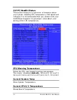
Страница 78: ... CPU FAN Speed 15340 RPM CHASSIS Fan Speed Current CPUFAN3 Speed 0 RPM 0 RPM IN0 IN1 IN2 1 00V 1 55V 3 32V 5V 5 13V 12V 12 22V 12V 12 28V 12V 12 22V VBAT V 3 28V 5VSB V 5 04V Shutdown Temperature Disabled Item Help Menu Level Move Enter Select PU PD Value F10 Save Esc Exit F1 General Help F5 Previous Value F6 Fail Safe Defaults F7 Optimized Default CPU Warning Temperature Select the CPU over heate...

Страница 79: ... Fan speed CHASSIS Fan Speed Shows CHASSIS Fan speed Shutdown Temperature Select the CPU over heated shutdown temperature The choice Disabled default 60 C 140 F 65 C 149 F 70 C 158 F 75 C 167 F 78 TR LCD1900 ITX 7 User Manual ...

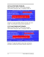
Страница 80: ...e most stable minimal performance system operations 3 10 Load Optimized Defaults When you press Enter on this item you get a confirmation dialog box with a message similar to Phoenix Award BIOS CMOS Setup Utility Stand CMOS Features Advanced BIOS Features Advance Chipset Features Integrated Peripherals Power Management PnP PCI Configuration PC Health Status Load Fail Safe Default Load Optimized De...

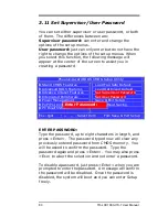
Страница 81: ...I Configuration PC Health Status Load Fail Safe Default Load Optimized Default Set Supervisor Password Set User Password Save Exit Setup Exit Without Saving Esc Quit Select Item F10 Save Exit Setup ENTER PASSWORD Type the password up to eight characters in length and press Enter The password typed now will clear any previously entered password from CMOS memory You will be asked to confirm the pass...

Страница 82: ...me you try to enter Setup This prevents an unauthorized person from changing any part of your system configuration Additionally when a password is enabled you can also require the BIOS to request a password every time your system is rebooted This would prevent unauthorized use of your computer You determine when the password is required within the BIOS Features Setup Menu and its Security option I...

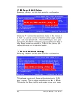
Страница 83: ... configures your system according to the Setup selections stored in CMOS After saving the values the system is restarted again 3 13 Exit Without Saving Pressing Enter on this item asks for confirmation Phoenix Award BIOS CMOS Setup Utility Stand CMOS Features Advanced BIOS Features Advance Chipset Features Integrated Peripherals Power Management PnP PCI Configuration PC Health Status Load Fail Saf...

Страница 84: ...ndix AC Power Adapter 84 I O Port Address Map 85 Interrupt Request Lines IRQ 86 POST Beep 87 Resistive Touchscreen Option 88 94 TR LCD1900 ITX 7 Mechanical Drawings 95 107 83 TR LCD1900 ITX 7 User Manual 83 ...

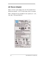
Страница 85: ...ow is the AC power adapter for the TR LCD1900 ITX 7 industrial computer A 6 HP style power cord is included Other voltages that are available for this system are 12V 24V 48V 125V and 250V DC 84 TR LCD1900 ITX 7 User Manual ...

Страница 86: ...0h 05Fh Timer 060h 06Fh Keyboard Controller 070h 07Fh Real Time Clock NMI 080h 09Fh DMA Page Register 0A0h 0BFh Interrupt Controller 2 0C0h 0DFh DMA Controller 2 0F0h Clear Math Coprocessor Busy Signal 0F1h Reset Math Coprocessor 1F0h 1F7h IDE Interface 278 27F Parallel Port 2 LPT2 2F8h 2FFh Serial Port 2 COM2 2B0 2DF Graphics adapter Controller 378h 3FFh Parallel Port 1 LPT1 360 36F Network Ports...

Страница 87: ...e IRQ used by the devices on the Industrial CPU Card Level Function IRQ0 System Timer Output IRQ1 Keyboard IRQ2 Interrupt Cascade IRQ3 Serial Port 2 IRQ4 Serial Port 1 IRQ5 Reserved IRQ6 Floppy Disk Controller IRQ7 Parallel Port 1 IRQ8 Real Time Clock IRQ9 Software Redirected to Int 0Ah IRQ10 Reserved IRQ11 Reserved IRQ12 PS 2 Mouse IRQ13 80287 IRQ14 Primary IDE IRQ15 Secondary IDE 86 TR LCD1900 I...

Страница 88: ...rred and the BIOS cannot initialize the video screen to display any additional information This beep code consists of a single long beep followed by two short beeps The other code indicates that your DRAM error has occurred This beep code consists of a single long beep repeatedly 87 TR LCD1900 ITX 7 User Manual ...

Страница 89: ...TX 7 is USB and follow the prompts accordingly Windows will copy the files to your hard drive and setup will be complete Windows XP will give a warning message about the TouchKit Controller certification press Continue anyway Please reboot your computer Windows will now find the device automatically and it will be listed in the Device Manager as TouchKit USB Controller TouchKit Software There are ...

Страница 90: ...requency drag the cursor from left to right low to high Duration Sound duration drag the cursor from left to right short to long Advanced A 25 Point calibration utility for the touch sensor Press Clear to clear previous calibration records Press 25 pts Cal to do 25 point calibration by touching the blinking symbol on the panel until you get a beep or it stops blinking After calibration the new rec...

Страница 91: ... rectangular box of Touch Tray Blue area indicates which button has been selected Shutdown utility Click on shutdown utility in the task bar Shutdown utility dialog There are five modes in shutdown utility Standby to enter standby mode that saves power consumption Shutdown to turn off PC Reboot to restart PC Cancel to escape from the Shutdown utility dialog Exit to disable the Shutdown utility Ple...

Страница 92: ...ick Adjustment Constant Touch Enable Constant Touch to force driver to stop reporting touch points when movement is slight You will see a stabilized cursor instead of a chattering cursor when users touch the same point Eliminates unwanted noise Auto Right Button Enable Auto Right Button to force driver to report a right click mouse event to OS when users lift up from a constant touch You no longer...

Страница 93: ... the edges of the screen image Top If you set the Edge to Smaller TouchKit will reduce the horizontal position of the top edge If you set the Edge to Larger TouchKit will extend the horizontal position of the top edge Bottom If you set the Edge to Smaller TouchKit will reduce the horizontal position of the bottom edge If you set the Edge to Larger TouchKit will extend the horizontal position of th...

Страница 94: ... 10 pixels from the X and Y Axis to the left and bottom Choose the Default button to restore the default settings In some cases the cursor will be behind the finger when you touch the panel If you cannot see the cursor you can set the X Axis or Y Axis to move the cursor Offset X Axis If you set the Offset X Axis to Smaller cursor will be moved one pixel to the left of the X Axis If you set the Off...

Страница 95: ...ping Press Apply to apply the mapping relationship Split Monitors To use the Split Monitor function you need to select which controller you want to launch this function then check the Multiple Monitors box and Split Monitor at the same time as shown below Press the Split Monitor button to set up the active area It shows the current resolution of the display and you can set the active area by input...

Страница 96: ......

Страница 97: ......

Страница 98: ......

Страница 99: ......

Страница 100: ......

Страница 101: ......

Страница 102: ......

Страница 103: ......

Страница 104: ......

Страница 105: ......

Страница 106: ......

Страница 107: ......

Отзывы: