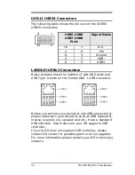
USB12 USB34 Connectors
The following table shows the pin outs of the USB56
USB78 connectors.
USB5,USB6
USB7,USB8
Pin#
Signal Name
10
1
N.C.
2
9
+5V
8
3
Ground
4
7
USB-
6
5
USB+
USBx2 Connectors
Below pictures show the location of LAN GbE ports and
USB Type-A ports on the Combo GbE + USB connector.
Before you connect your device(s) into USB connector(s),
please make sure your device(s) such as USB keyboard,
mouse, scanner, zip, speaker and etc., Have a standard
USB interface. Also make sure your OS supports USB
controller.
If you‟re OS does not support USB controller, please
contact OS vendor for possible patch or driver upgrade.
For more information please contact your OS or device(s)
vendors.
1
9
2
10
32
TR-LCD1900-ITX-7 User Manual
Содержание TR-LCD1900-ITX-7
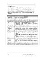
Страница 17: ...Jumper Locations on the TR LCD1900 ITX 7 16 TR LCD1900 ITX 7 User Manual ...
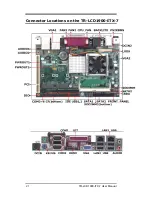
Страница 22: ...Connector Locations on the TR LCD1900 ITX 7 21 TR LCD1900 ITX 7 User Manual ...
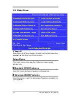
Страница 46: ... Exit Without Saving Abandon all CMOS value changes and exit setup 45 TR LCD1900 ITX 7 User Manual ...
Страница 96: ......
Страница 97: ......
Страница 98: ......
Страница 99: ......
Страница 100: ......
Страница 101: ......
Страница 102: ......
Страница 103: ......
Страница 104: ......
Страница 105: ......
Страница 106: ......
Страница 107: ......


