83
TRAK Machine Tools
Southwestern Industries, Inc.
ProtoTRAK SMX, K2, K3 & K4 & Retrofit Safety, Installation, Maintenance, Service and Parts List Manual
CAUTION!
After the reader head is attached to the reader head-mounting bracket, do not move
the machine axis until the shipping bracket is removed. This will break the reader
head. This is not covered under warranty.
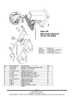
See Figure 29 for an illustration of how to align glass scales.
5.1.7.3 Install the Z-Axis Glass Scale
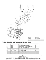
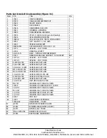
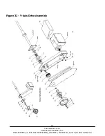
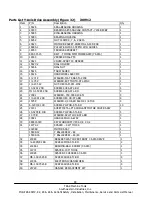
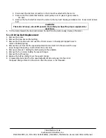
See Figure 28.
1.
Check the tram of the head in the X direction. If it is within a few thousands then continue on. If not tram.
2.
Assemble Z-axis glass scale mounting bracket and mount to head. Items 1, 2, 3 and 4. Tap items 3 and 4 together
and tap item 3 into the quill stop knob. Leave the bolt loose. Use 2 screws (item 6) and mount item 4 to the side of
item 2 using a spacer between both items to provide a gap of approximately 0.040” between Items 2 and 4. This is
to make sure item 2 does not rub against item 4.
3.
Align the glass scale bracket (Item 2) with an indicator and tighten the mounting screws. Leave the quill stop knob
screws loose. Remove the spacer and bolts from Item 4.
4.
Unscrew the shipping protection screw from the scale.
5.
Mount the glass scale to the mounting bracket and align it with an indicator. It needs to be aligned within 0.008"
with respect to the quill. Tighten the screws down.
6.
Fasten the readerhead to the readerhead bracket.
7.
Move the readerhead up and down the glass scale and make sure the gap is consistent between the readerhead and
the glass scale. Tighten the screw to the quill stop knob.
8.
Remove the red head securing plate.
9.
If the gap is not consistent between the readerhead and the glass scale when moving the quill up and down then
adjust the angle of the scale to make the gap consistent.
CAUTION!
The gap must be no larger than 0.060” between the readerhead and glass scale.

