103
TRAK Machine Tools
Southwestern Industries, Inc.
ProtoTRAK SMX, K2, K3 & K4 & Retrofit Safety, Installation, Maintenance, Service and Parts List Manual
5.
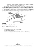
Lift the end of the table up and note the amount of movement on the dial indicator. Adjust the Y-axis left
bottom gib until the registered movement is .0010-.0015.
6.
Move the table fully to the right.
7.
Reposition the indicator to the right front of the saddle.
8.
Lift the right end of the table up and note the amount of movement on the dial indicator. Adjust the Y-axis
right bottom gib until the registered movement is .0010-.0015.
To adjust the gib for excessive clearance:
Loosen the gib lock screw on the back of the saddle. Estimate the amount of gib lock screw adjustment required, and
tighten the gib lock screw on the front of the saddle. Tighten the gib lock screw on the back end of the saddle to lock
the gib in place, and recheck. Repeat as necessary.
To adjust the gib for too small of a clearance:
Loosen the gib lock screw on the front of the saddle. Estimate the amount of gib lock screw adjustment
required and tighten the gib lock screw on the back of the saddle. Tighten the gib lock screw on the front of
the saddle to lock the gib in place, and recheck. Repeat as necessary.
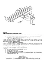
Figure 42
Saddle Bottom Gib Adjustment (K3 & K4 Only)
5.2.2 Calibration & Backlash Constants
Calibration and backlash constants were set as part of the installation and set-up of your system. They
should be re-set when indicated in the Troubleshooting section or after the replacement of the Computer
module, or any parts of the drive train.

