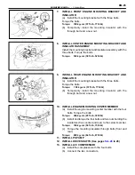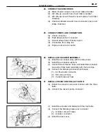
7. INSTALL FRONT ENGINE MOUNTING BRACKET AND
INSULATOR
(a) Install the mounting bracket with the three bolts.
Torque the bolts.
Torque: 790 kg–cm (57 ft–lb, 77 N
⋅
m)
(b) Temporarily install the mounting insulator with the
through bolt and a new nut.
8.
INSTALL CENTER ENGINE MOUNTING BRACKET AND
INSULATOR ASSEMBLY
Install the mounting bracket and insulator assembly with the
three bolts. Torque the bolts.
Torque: 530 kg–cm (38 ft–lb, 52 N
⋅
m)
9. INSTALL
REAR
ENGINE
MOUNTING
BRACKET
AND
INSULATOR
(a) Install the mounting bracket with the three bolts.
Torque the bolts.
Torque: 790 kg–cm (57 ft–lb, 77 N
⋅
m)
(b) Temporarily install the mounting insulator with the
through bolt and a new nut.
10. INSTALL ENGINE MOUNTING CENTER MEMBER
(a) Install the engine mounting center member with the four
bolts. Torque the bolts.
Torque: 400 kg–cm (29 ft–lb, 39 N
⋅
m)
(b) Install and torque the four bolts and two nuts holding the
insulators (front, center and rear) to the center member.
Torque: 740 kg–cm (54 ft–lb, 73 N
⋅
m)
(c) Torque the mounting insulator through bolts (front and
rear).
Torque: 890 kg–cm (64 ft–lb, 87 N
⋅
m)
11. INSTALL PS PUMP
12. INSTALL DRIVE SHAFTS (See pages
to 28)
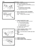
13. INSTALL A/C COMPRESSOR
(a) Install the compressor with the four bolts.
(b) Connect the two connectors.
EM-95
ENGINE MECHANICAL – Cylinder Block
Содержание 2VZ-FE
Страница 1: ...ENGINE MECHANICAL EM 1 ENGINE MECHANICAL Description Operation ...
Страница 31: ...CYLINDER HEADS COMPONENTS EM 29 ENGINE MECHANICAL Cylinder Heads ...
Страница 63: ...CYLINDER BLOCK REMOVAL OF ENGINE EM 61 ENGINE MECHANICAL Cylinder Block ...
Страница 64: ...EM 62 ENGINE MECHANICAL Cylinder Block ...
Страница 71: ...COMPONENTS EM 69 ENGINE MECHANICAL Cylinder Block ...
Страница 106: ...EFI SYSTEM FI 1 ...
Страница 107: ...DESCRIPTION FI 2 EFI SYSTEM Description ...
Страница 111: ...OPERATION System Circuit FI 4 EFI SYSTEM Operation System Circuit ...
Страница 121: ...FUEL SYSTEM Fuel Pump EFI SYSTEM Fuel System Fuel Pump FI 15 ...
Страница 141: ...Fuel Tank and Lines COMPONENTS EFI SYSTEM Fuel System Fuel Tank and Lines FI 35 ...
Страница 172: ...EXHAUST SYSTEM EXHAUST SYSTEM REPAIR INSTRUCTIONS EX 1 ...
Страница 173: ...EXHAUST PIPES AND HEAT INSULATORS COMPONENTS EX 2 EXHAUST SYSTEM Exhaust Pipes and Heat Insulators ...
Страница 174: ...EMISSION CONTROL SYSTEMS EC 1 ...
Страница 176: ...COMPONENT LAYOUT AND SCHEMATIC DRAWING EMISSION CONTROL SYSTEMS Component Layout and Schematic Drawing EC 3 ...
Страница 186: ...COOLING SYSTEM CO 1 ...
Страница 205: ...LUBRICATION SYSTEM LUBRICATION SYSTEM Description Operation LU 1 ...
Страница 223: ...SERVICE SPECIFICATIONS SPECIFICATIONS TORQUE SPECIFICATIONS LU 18 LUBRICATION SYSTEM ServiceSpecifications ...
Страница 224: ...IGNITION SYSTEM IG 1 ...
Страница 237: ...SERVICE SPECIFICATIONS IG 14 IGNITION SYSTEM ServiceSpecifications ...
Страница 238: ...ENGINE TROUBLESHOOTING TR 1 ...
Страница 268: ...DIAGNOSTIC CHART WIRING DIAGRAM AND ECU CONNECTORS ENGINE TROUBLESHOOTING CircuitInspection TR 31 ...
Страница 285: ...DIAGNOSTIC CHART WIRING DIAGRAM AND ECU CONNECTORS TR 48 ENGINE TROUBLESHOOTING CircuitInspection ...
Страница 292: ...DIAGNOSTIC CHART WIRING DIAGRAM AND ECU CONNECTORS ENGINE TROUBLESHOOTING CircuitInspection TR 55 ...
Страница 301: ...DIAGNOSTIC CHART WIRING DIAGRAM AND ECU CONNECTORS TR 64 ENGINE TROUBLESHOOTING CircuitInspection ...
Страница 315: ...DIAGNOSTIC CHART WIRING DIAGRAM AND ECU CONNECTORS TR 78 ENGINE TROUBLESHOOTING CircuitInspection ...
Страница 320: ...DIAGNOSTIC CHART WIRING DIAGRAM AND ECU CONNECTORS ENGINE TROUBLESHOOTING CircuitInspection TR 83 ...


