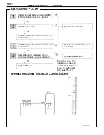
Replace ECU. *
Repair or relace harness or connector.
Check voltage between terminal VC of
throttle position sensor connector and body
ground.
Check voltage between terminals VC and
E2 of ECU connector.
Check for short circuit between ECU and
throttle position sensor.
Replace ECU.
Check harness and connector
between ECU and throttle
position sensor.
Check for open circuit between
ECU and throttle position sensor.
Check harness and connector
between ECU and throttle
position sensor.
* When diag. code 41 is not
displayed, proceed to next circuit
inspection shown on matrix chart
(See page
Diag. Code
41
Throttle Position Sensor Signal
CIRCUIT DESCRIPTION
The throttle position sensor is provided to the throttle body and detects the opening angle of the
throttle valve.
The ECU judges the vehicle driving conditions from the signals input from the terminal VTA of the
throttle position sensor.
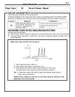
Code No.
Diagnosis
Trouble Area
41
Open or short circuit in throttle position
sensor signal (VTA).
·
Open or short in throttle position sensor cir-
cuit.
41
IDL contact is ON and VTA output
exceeds 1.45 V.
·
Throttle position sensor
·
ECU
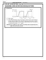
HINT: When the connector for the throttle position sensor is disconnected, diagnostic code 41 is not
output. Diagnostic code 41 is output only when there is an open or short in the VTA signal circuit of
the throttle position sensor.
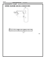
DIAGNOSTIC CHART
Check voltage between terminals VC and
E2 of throttle position sensor connector.
Check throttle position sensor.
Replace ECU. *
Repair or relace harness or connector.
Check voltage between terminal VC of
throttle position sensor connector and body
ground.
Check voltage between terminals VTA and
E2 of ECU connector.
Check voltage between terminals VC and
E2 of ECU connector.
Check for short circuit between ECU and
throttle position sensor.
Replace ECU.
Check harness and connector
between ECU and throttle
position sensor.
Check for open circuit between
ECU and throttle position sensor.
Check harness and connector
between ECU and throttle
position sensor.
Adjust or replace throttle position
sensor.
* When diag. code 41 is not
displayed, proceed to next circuit
inspection shown on matrix chart
(See page
–
ENGINE TROUBLESHOOTING
Circuit Inspection
TR–63
Содержание 2VZ-FE
Страница 1: ...ENGINE MECHANICAL EM 1 ENGINE MECHANICAL Description Operation ...
Страница 31: ...CYLINDER HEADS COMPONENTS EM 29 ENGINE MECHANICAL Cylinder Heads ...
Страница 63: ...CYLINDER BLOCK REMOVAL OF ENGINE EM 61 ENGINE MECHANICAL Cylinder Block ...
Страница 64: ...EM 62 ENGINE MECHANICAL Cylinder Block ...
Страница 71: ...COMPONENTS EM 69 ENGINE MECHANICAL Cylinder Block ...
Страница 106: ...EFI SYSTEM FI 1 ...
Страница 107: ...DESCRIPTION FI 2 EFI SYSTEM Description ...
Страница 111: ...OPERATION System Circuit FI 4 EFI SYSTEM Operation System Circuit ...
Страница 121: ...FUEL SYSTEM Fuel Pump EFI SYSTEM Fuel System Fuel Pump FI 15 ...
Страница 141: ...Fuel Tank and Lines COMPONENTS EFI SYSTEM Fuel System Fuel Tank and Lines FI 35 ...
Страница 172: ...EXHAUST SYSTEM EXHAUST SYSTEM REPAIR INSTRUCTIONS EX 1 ...
Страница 173: ...EXHAUST PIPES AND HEAT INSULATORS COMPONENTS EX 2 EXHAUST SYSTEM Exhaust Pipes and Heat Insulators ...
Страница 174: ...EMISSION CONTROL SYSTEMS EC 1 ...
Страница 176: ...COMPONENT LAYOUT AND SCHEMATIC DRAWING EMISSION CONTROL SYSTEMS Component Layout and Schematic Drawing EC 3 ...
Страница 186: ...COOLING SYSTEM CO 1 ...
Страница 205: ...LUBRICATION SYSTEM LUBRICATION SYSTEM Description Operation LU 1 ...
Страница 223: ...SERVICE SPECIFICATIONS SPECIFICATIONS TORQUE SPECIFICATIONS LU 18 LUBRICATION SYSTEM ServiceSpecifications ...
Страница 224: ...IGNITION SYSTEM IG 1 ...
Страница 237: ...SERVICE SPECIFICATIONS IG 14 IGNITION SYSTEM ServiceSpecifications ...
Страница 238: ...ENGINE TROUBLESHOOTING TR 1 ...
Страница 268: ...DIAGNOSTIC CHART WIRING DIAGRAM AND ECU CONNECTORS ENGINE TROUBLESHOOTING CircuitInspection TR 31 ...
Страница 285: ...DIAGNOSTIC CHART WIRING DIAGRAM AND ECU CONNECTORS TR 48 ENGINE TROUBLESHOOTING CircuitInspection ...
Страница 292: ...DIAGNOSTIC CHART WIRING DIAGRAM AND ECU CONNECTORS ENGINE TROUBLESHOOTING CircuitInspection TR 55 ...
Страница 301: ...DIAGNOSTIC CHART WIRING DIAGRAM AND ECU CONNECTORS TR 64 ENGINE TROUBLESHOOTING CircuitInspection ...
Страница 315: ...DIAGNOSTIC CHART WIRING DIAGRAM AND ECU CONNECTORS TR 78 ENGINE TROUBLESHOOTING CircuitInspection ...
Страница 320: ...DIAGNOSTIC CHART WIRING DIAGRAM AND ECU CONNECTORS ENGINE TROUBLESHOOTING CircuitInspection TR 83 ...


