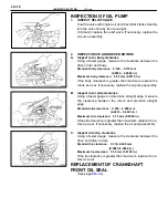
(b) Apply seal packing to the baffle plate as shown in the
figure.
Seal packing: Part No. 08826–00080 or equivalent
•
Install a nozzle that has been cut to a 3–4 mm
(0.12–0.16 in.) opening.
HINT: Avoid applying an excessive amount to the surface.
•
Parts must be assembled within 5 minutes of
application. Otherwise the material must be
removed and reapplied.
•
Immediately remove nozzle from the tube and
re–install cap.
(c) Install the baffle plate.
10. INSTALL OIL PAN
(a) Remove any old packing (FIPG) material and be careful
not to drop any oil on the contact surfaces of the oil pan
and cylinder block.
•
Using a razor blade and gasket scraper, remove all
the old packing (FIPG) material from the gasket
surfaces and sealing grooves.
•
Thoroughly clean all components to remove all the
loose material.
•
Using a non–residue solvent, clean both sealing
surfaces.
NOTICE: Do not use a solvent which will affect the
painted surfaces.
(b) Apply seal packing to the oil pan as shown in the figure.
Seal packing: Part No. 08826–00080 or equivalent
•
Install a nozzle that has been cut to a 3–4 mm
(0.12–0.16 in.) opening.
HINT: Avoid applying an excessive amount to the surface.
•
Parts must be assembled within 5 minutes of
application. Otherwise the material must be
removed and reapplied.
•
Immediately remove nozzle from the tube and
reinstall cap.
LU–16
–
LUBRICATION SYSTEM
Oil Pump
Содержание 2VZ-FE
Страница 1: ...ENGINE MECHANICAL EM 1 ENGINE MECHANICAL Description Operation ...
Страница 31: ...CYLINDER HEADS COMPONENTS EM 29 ENGINE MECHANICAL Cylinder Heads ...
Страница 63: ...CYLINDER BLOCK REMOVAL OF ENGINE EM 61 ENGINE MECHANICAL Cylinder Block ...
Страница 64: ...EM 62 ENGINE MECHANICAL Cylinder Block ...
Страница 71: ...COMPONENTS EM 69 ENGINE MECHANICAL Cylinder Block ...
Страница 106: ...EFI SYSTEM FI 1 ...
Страница 107: ...DESCRIPTION FI 2 EFI SYSTEM Description ...
Страница 111: ...OPERATION System Circuit FI 4 EFI SYSTEM Operation System Circuit ...
Страница 121: ...FUEL SYSTEM Fuel Pump EFI SYSTEM Fuel System Fuel Pump FI 15 ...
Страница 141: ...Fuel Tank and Lines COMPONENTS EFI SYSTEM Fuel System Fuel Tank and Lines FI 35 ...
Страница 172: ...EXHAUST SYSTEM EXHAUST SYSTEM REPAIR INSTRUCTIONS EX 1 ...
Страница 173: ...EXHAUST PIPES AND HEAT INSULATORS COMPONENTS EX 2 EXHAUST SYSTEM Exhaust Pipes and Heat Insulators ...
Страница 174: ...EMISSION CONTROL SYSTEMS EC 1 ...
Страница 176: ...COMPONENT LAYOUT AND SCHEMATIC DRAWING EMISSION CONTROL SYSTEMS Component Layout and Schematic Drawing EC 3 ...
Страница 186: ...COOLING SYSTEM CO 1 ...
Страница 205: ...LUBRICATION SYSTEM LUBRICATION SYSTEM Description Operation LU 1 ...
Страница 223: ...SERVICE SPECIFICATIONS SPECIFICATIONS TORQUE SPECIFICATIONS LU 18 LUBRICATION SYSTEM ServiceSpecifications ...
Страница 224: ...IGNITION SYSTEM IG 1 ...
Страница 237: ...SERVICE SPECIFICATIONS IG 14 IGNITION SYSTEM ServiceSpecifications ...
Страница 238: ...ENGINE TROUBLESHOOTING TR 1 ...
Страница 268: ...DIAGNOSTIC CHART WIRING DIAGRAM AND ECU CONNECTORS ENGINE TROUBLESHOOTING CircuitInspection TR 31 ...
Страница 285: ...DIAGNOSTIC CHART WIRING DIAGRAM AND ECU CONNECTORS TR 48 ENGINE TROUBLESHOOTING CircuitInspection ...
Страница 292: ...DIAGNOSTIC CHART WIRING DIAGRAM AND ECU CONNECTORS ENGINE TROUBLESHOOTING CircuitInspection TR 55 ...
Страница 301: ...DIAGNOSTIC CHART WIRING DIAGRAM AND ECU CONNECTORS TR 64 ENGINE TROUBLESHOOTING CircuitInspection ...
Страница 315: ...DIAGNOSTIC CHART WIRING DIAGRAM AND ECU CONNECTORS TR 78 ENGINE TROUBLESHOOTING CircuitInspection ...
Страница 320: ...DIAGNOSTIC CHART WIRING DIAGRAM AND ECU CONNECTORS ENGINE TROUBLESHOOTING CircuitInspection TR 83 ...

