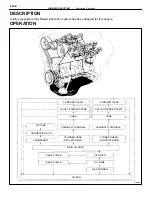
A Pressure feeding lubrication system has been adopted to supply oil to the moving parts of this engine.
The lubrication system consists of an oil pan, oil pump, oil filter and other external parts which supply oil to the
moving parts in the engine block. The oil circuit is shown in the illustration at the top of the previous page. Oil
from the oil pan is pumped up by the oil pump. After it passes through the oil filter, it is fed through the various
oil holes in the crankshaft and cylinder block. After passing through the cylinder block and performing its lubricat-
ing function, the oil is returned by gravity to the oil pan. A dipstick on the center left side of the cylinder block
is provided to check the oil level.
OIL PUMP
The oil pump pumps up oil from the oil pan and sends it under pressure to the various parts of the engine.
An oil strainer is mounted in front of the inlet to the oil pump. The oil pump itself is a trochoid type pump. inside
of which there is a drive rotor and a driven rotor. When the drive rotor rotates, the driven rotor rotates in the same
direction, and since the axis of the driven rotor shaft is different from the center of the driven rotor, the space
between the two rotors is changed as they rotate. Oil is drawn in when the space is wide and is discharged when
the space in narrow.
OIL PRESSURE REGULATOR
At high engine speeds, the engine oil supplied by the oil pump exceeds the capacity of the engine to utilize
it. For that reason, the oil pressure regulator works to prevent an oversupply of oil. During normal oil supply, a
coil spring and valve keep the bypass closed, but when too much oil is being fed, the pressure become extremely
high, overpowering the force of the spring and opening the valves. This allows the excess oil to flow through
the relief valve and return to the oil pan.
OIL FILTER
The oil filter is a full flow type filter with a built–in paper filter element. Particles of metal from wear, airborn
dirt, carbon and other impurities can get into the oil during use and could cause accelerated wear or sizing if
allowed to circulate through the engine. The oil filter, integrated into the oil line, removes these impurities as the
oil passes through it. The filter is mounted outside the engine to simplify replacement of the filter element. A relief
valve is also included ahead of the filter element to relieve the high oil pressure in case that the filter element
becomes clogged with impurities. The relief valve opens when the oil pressure overpowers the force of the
spring. Oil passing through the relief valve by–passes the oil filter and flows directly into the main oil hole in the
engine.
–
LUBRICATION SYSTEM
Operation
LU–3
Содержание 2VZ-FE
Страница 1: ...ENGINE MECHANICAL EM 1 ENGINE MECHANICAL Description Operation ...
Страница 31: ...CYLINDER HEADS COMPONENTS EM 29 ENGINE MECHANICAL Cylinder Heads ...
Страница 63: ...CYLINDER BLOCK REMOVAL OF ENGINE EM 61 ENGINE MECHANICAL Cylinder Block ...
Страница 64: ...EM 62 ENGINE MECHANICAL Cylinder Block ...
Страница 71: ...COMPONENTS EM 69 ENGINE MECHANICAL Cylinder Block ...
Страница 106: ...EFI SYSTEM FI 1 ...
Страница 107: ...DESCRIPTION FI 2 EFI SYSTEM Description ...
Страница 111: ...OPERATION System Circuit FI 4 EFI SYSTEM Operation System Circuit ...
Страница 121: ...FUEL SYSTEM Fuel Pump EFI SYSTEM Fuel System Fuel Pump FI 15 ...
Страница 141: ...Fuel Tank and Lines COMPONENTS EFI SYSTEM Fuel System Fuel Tank and Lines FI 35 ...
Страница 172: ...EXHAUST SYSTEM EXHAUST SYSTEM REPAIR INSTRUCTIONS EX 1 ...
Страница 173: ...EXHAUST PIPES AND HEAT INSULATORS COMPONENTS EX 2 EXHAUST SYSTEM Exhaust Pipes and Heat Insulators ...
Страница 174: ...EMISSION CONTROL SYSTEMS EC 1 ...
Страница 176: ...COMPONENT LAYOUT AND SCHEMATIC DRAWING EMISSION CONTROL SYSTEMS Component Layout and Schematic Drawing EC 3 ...
Страница 186: ...COOLING SYSTEM CO 1 ...
Страница 205: ...LUBRICATION SYSTEM LUBRICATION SYSTEM Description Operation LU 1 ...
Страница 223: ...SERVICE SPECIFICATIONS SPECIFICATIONS TORQUE SPECIFICATIONS LU 18 LUBRICATION SYSTEM ServiceSpecifications ...
Страница 224: ...IGNITION SYSTEM IG 1 ...
Страница 237: ...SERVICE SPECIFICATIONS IG 14 IGNITION SYSTEM ServiceSpecifications ...
Страница 238: ...ENGINE TROUBLESHOOTING TR 1 ...
Страница 268: ...DIAGNOSTIC CHART WIRING DIAGRAM AND ECU CONNECTORS ENGINE TROUBLESHOOTING CircuitInspection TR 31 ...
Страница 285: ...DIAGNOSTIC CHART WIRING DIAGRAM AND ECU CONNECTORS TR 48 ENGINE TROUBLESHOOTING CircuitInspection ...
Страница 292: ...DIAGNOSTIC CHART WIRING DIAGRAM AND ECU CONNECTORS ENGINE TROUBLESHOOTING CircuitInspection TR 55 ...
Страница 301: ...DIAGNOSTIC CHART WIRING DIAGRAM AND ECU CONNECTORS TR 64 ENGINE TROUBLESHOOTING CircuitInspection ...
Страница 315: ...DIAGNOSTIC CHART WIRING DIAGRAM AND ECU CONNECTORS TR 78 ENGINE TROUBLESHOOTING CircuitInspection ...
Страница 320: ...DIAGNOSTIC CHART WIRING DIAGRAM AND ECU CONNECTORS ENGINE TROUBLESHOOTING CircuitInspection TR 83 ...


