Diag. Code
51
Switch Condition Signal
CIRCUIT DESCRIPTION
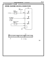
Neutral Start Switch Signal
The ECU uses the signals from the neutral start switch to determine whether the transmission is in
park or neutral, or in some other gear.
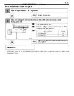
Air Conditioner Switch Signal
The ECU uses the signal from the air conditioner switch to determine whether or not the air conditioner
is operating, and increases the idling speed of the engine.
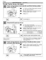
Throttle Position Sensor IDL Signal
The IDL contacts are provided in the throttle position sensor, and detects the idle condition.
Code No.
Diagnosis
Trouble Area
51
Displayed when A/C is ON, IDL contact
OFF or shift position in “R”, “D”, “2”, or
“1” renges with the check terminals E1
and TE1 connected.
·
A/C switch circuit
·
Throttle position sensor IDL circuit
·
Neutral start switch circuit
·
Accelerator pedal, cable
·
ECU
DIAGNOSTIC CHART
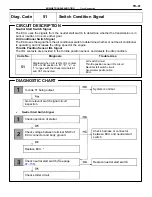
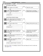
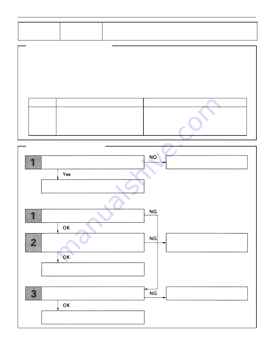
Is code 51 being output.
Go to relevant switch signal circuit
inspection.
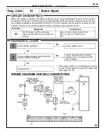
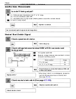
Check operation of starter.
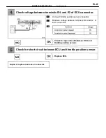
Check voltage between terminal NSW of
ECU connector and body ground.
Replace ECU. *
Check neutral start switch (See page
).
Check starter circuit.
Replace nuetral start switch.
Check harness or connector
between ECU and neutral start
switch.
System is normal.
•
Neutral Start Switch Signal
–
ENGINE TROUBLESHOOTING
Circuit Inspection
TR–81
Содержание 2VZ-FE
Страница 1: ...ENGINE MECHANICAL EM 1 ENGINE MECHANICAL Description Operation ...
Страница 31: ...CYLINDER HEADS COMPONENTS EM 29 ENGINE MECHANICAL Cylinder Heads ...
Страница 63: ...CYLINDER BLOCK REMOVAL OF ENGINE EM 61 ENGINE MECHANICAL Cylinder Block ...
Страница 64: ...EM 62 ENGINE MECHANICAL Cylinder Block ...
Страница 71: ...COMPONENTS EM 69 ENGINE MECHANICAL Cylinder Block ...
Страница 106: ...EFI SYSTEM FI 1 ...
Страница 107: ...DESCRIPTION FI 2 EFI SYSTEM Description ...
Страница 111: ...OPERATION System Circuit FI 4 EFI SYSTEM Operation System Circuit ...
Страница 121: ...FUEL SYSTEM Fuel Pump EFI SYSTEM Fuel System Fuel Pump FI 15 ...
Страница 141: ...Fuel Tank and Lines COMPONENTS EFI SYSTEM Fuel System Fuel Tank and Lines FI 35 ...
Страница 172: ...EXHAUST SYSTEM EXHAUST SYSTEM REPAIR INSTRUCTIONS EX 1 ...
Страница 173: ...EXHAUST PIPES AND HEAT INSULATORS COMPONENTS EX 2 EXHAUST SYSTEM Exhaust Pipes and Heat Insulators ...
Страница 174: ...EMISSION CONTROL SYSTEMS EC 1 ...
Страница 176: ...COMPONENT LAYOUT AND SCHEMATIC DRAWING EMISSION CONTROL SYSTEMS Component Layout and Schematic Drawing EC 3 ...
Страница 186: ...COOLING SYSTEM CO 1 ...
Страница 205: ...LUBRICATION SYSTEM LUBRICATION SYSTEM Description Operation LU 1 ...
Страница 223: ...SERVICE SPECIFICATIONS SPECIFICATIONS TORQUE SPECIFICATIONS LU 18 LUBRICATION SYSTEM ServiceSpecifications ...
Страница 224: ...IGNITION SYSTEM IG 1 ...
Страница 237: ...SERVICE SPECIFICATIONS IG 14 IGNITION SYSTEM ServiceSpecifications ...
Страница 238: ...ENGINE TROUBLESHOOTING TR 1 ...
Страница 268: ...DIAGNOSTIC CHART WIRING DIAGRAM AND ECU CONNECTORS ENGINE TROUBLESHOOTING CircuitInspection TR 31 ...
Страница 285: ...DIAGNOSTIC CHART WIRING DIAGRAM AND ECU CONNECTORS TR 48 ENGINE TROUBLESHOOTING CircuitInspection ...
Страница 292: ...DIAGNOSTIC CHART WIRING DIAGRAM AND ECU CONNECTORS ENGINE TROUBLESHOOTING CircuitInspection TR 55 ...
Страница 301: ...DIAGNOSTIC CHART WIRING DIAGRAM AND ECU CONNECTORS TR 64 ENGINE TROUBLESHOOTING CircuitInspection ...
Страница 315: ...DIAGNOSTIC CHART WIRING DIAGRAM AND ECU CONNECTORS TR 78 ENGINE TROUBLESHOOTING CircuitInspection ...
Страница 320: ...DIAGNOSTIC CHART WIRING DIAGRAM AND ECU CONNECTORS ENGINE TROUBLESHOOTING CircuitInspection TR 83 ...

