SYMPTOM SIMULATION
”Intermittent troubles or problems” are the malfunctions about which the customer has a complaint, but which
do not occur and can not be confirmed in the workshop. The intermittent problems also include complaints about
the ”CHECK” engine warning light going on and off erratically.
The self–diagnostic system stores the circuit of the intermittent problem in memory even if the ignition switch
is turned off.
And, for accurate diagnosis of the problems, ask the customer to obtain information as much as possible follow-
ing the customer problem analysis check sheet (See page
), and try to reproduce the intermittent problem.
The problem simulation methods described below are the effective ways for this nature of problem to produce
the problem conditions by applying vibration, heat, and humidity.
1
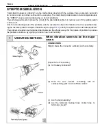
VIBRATION METHOD:
When vibration seems to be the major
cause.
CONNECTORS
Slightly shake the connector vertically and horizontally.
(Inspection of connectors)
(a) Is it loosely connected?
(b) Does the wire harness connecting with its
corresponding part have insufficient slack?
(c) Are the terminals dirty?
(d) Are the terminals making loose contact due to
terminals spread?
TR–14
–
ENGINE TROUBLESHOOTING
Symtom Simulation
Содержание 2VZ-FE
Страница 1: ...ENGINE MECHANICAL EM 1 ENGINE MECHANICAL Description Operation ...
Страница 31: ...CYLINDER HEADS COMPONENTS EM 29 ENGINE MECHANICAL Cylinder Heads ...
Страница 63: ...CYLINDER BLOCK REMOVAL OF ENGINE EM 61 ENGINE MECHANICAL Cylinder Block ...
Страница 64: ...EM 62 ENGINE MECHANICAL Cylinder Block ...
Страница 71: ...COMPONENTS EM 69 ENGINE MECHANICAL Cylinder Block ...
Страница 106: ...EFI SYSTEM FI 1 ...
Страница 107: ...DESCRIPTION FI 2 EFI SYSTEM Description ...
Страница 111: ...OPERATION System Circuit FI 4 EFI SYSTEM Operation System Circuit ...
Страница 121: ...FUEL SYSTEM Fuel Pump EFI SYSTEM Fuel System Fuel Pump FI 15 ...
Страница 141: ...Fuel Tank and Lines COMPONENTS EFI SYSTEM Fuel System Fuel Tank and Lines FI 35 ...
Страница 172: ...EXHAUST SYSTEM EXHAUST SYSTEM REPAIR INSTRUCTIONS EX 1 ...
Страница 173: ...EXHAUST PIPES AND HEAT INSULATORS COMPONENTS EX 2 EXHAUST SYSTEM Exhaust Pipes and Heat Insulators ...
Страница 174: ...EMISSION CONTROL SYSTEMS EC 1 ...
Страница 176: ...COMPONENT LAYOUT AND SCHEMATIC DRAWING EMISSION CONTROL SYSTEMS Component Layout and Schematic Drawing EC 3 ...
Страница 186: ...COOLING SYSTEM CO 1 ...
Страница 205: ...LUBRICATION SYSTEM LUBRICATION SYSTEM Description Operation LU 1 ...
Страница 223: ...SERVICE SPECIFICATIONS SPECIFICATIONS TORQUE SPECIFICATIONS LU 18 LUBRICATION SYSTEM ServiceSpecifications ...
Страница 224: ...IGNITION SYSTEM IG 1 ...
Страница 237: ...SERVICE SPECIFICATIONS IG 14 IGNITION SYSTEM ServiceSpecifications ...
Страница 238: ...ENGINE TROUBLESHOOTING TR 1 ...
Страница 268: ...DIAGNOSTIC CHART WIRING DIAGRAM AND ECU CONNECTORS ENGINE TROUBLESHOOTING CircuitInspection TR 31 ...
Страница 285: ...DIAGNOSTIC CHART WIRING DIAGRAM AND ECU CONNECTORS TR 48 ENGINE TROUBLESHOOTING CircuitInspection ...
Страница 292: ...DIAGNOSTIC CHART WIRING DIAGRAM AND ECU CONNECTORS ENGINE TROUBLESHOOTING CircuitInspection TR 55 ...
Страница 301: ...DIAGNOSTIC CHART WIRING DIAGRAM AND ECU CONNECTORS TR 64 ENGINE TROUBLESHOOTING CircuitInspection ...
Страница 315: ...DIAGNOSTIC CHART WIRING DIAGRAM AND ECU CONNECTORS TR 78 ENGINE TROUBLESHOOTING CircuitInspection ...
Страница 320: ...DIAGNOSTIC CHART WIRING DIAGRAM AND ECU CONNECTORS ENGINE TROUBLESHOOTING CircuitInspection TR 83 ...


