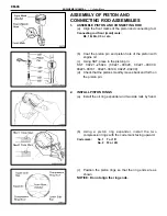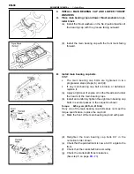
6. REMOVE
MAIN
BEARING
CAP
AND
CHECK
OIL
CLEARANCE
(a) Uniformly loosen and remove the main bearing cap
bolts in several passes in the sequence shown.
(b) Using a screwdriver, pry up the main bearing cap, and
remove the main bearing cap, lower main bearings and
lower thrust washers (No.2 journal position of main
bearing cap only).
HINT: Keep the lower main bearings and lower thrust wash-
ers together with the main bearing cap.
(c) Lift out the crankshaft.
HINT: Keep the upper main bearings and upper thrust wash-
ers together with the cylinder block.
(d) Clean each main journal and bearing.
(e) Check each main journal and bearing for pitting and
scratches.
If the journal or bearing is damaged, replace the bearings.
If necessary, grind or replace the crankshaft.
(f) Place the crankshaft on the cylinder block.
(g) Lay a strip of Plastigage across each journal.
(h) Install the main bearing cap with the eight bolts.
(See step 4 on page
)
Torque: 1st 625 kg–cm (45 ft–lb, 61 N
⋅
m)
2nd turn 90
°
NOTICE: Do not turn the crankshaft.
EM-74
ENGINE MECHANICAL – Cylinder Block
Содержание 2VZ-FE
Страница 1: ...ENGINE MECHANICAL EM 1 ENGINE MECHANICAL Description Operation ...
Страница 31: ...CYLINDER HEADS COMPONENTS EM 29 ENGINE MECHANICAL Cylinder Heads ...
Страница 63: ...CYLINDER BLOCK REMOVAL OF ENGINE EM 61 ENGINE MECHANICAL Cylinder Block ...
Страница 64: ...EM 62 ENGINE MECHANICAL Cylinder Block ...
Страница 71: ...COMPONENTS EM 69 ENGINE MECHANICAL Cylinder Block ...
Страница 106: ...EFI SYSTEM FI 1 ...
Страница 107: ...DESCRIPTION FI 2 EFI SYSTEM Description ...
Страница 111: ...OPERATION System Circuit FI 4 EFI SYSTEM Operation System Circuit ...
Страница 121: ...FUEL SYSTEM Fuel Pump EFI SYSTEM Fuel System Fuel Pump FI 15 ...
Страница 141: ...Fuel Tank and Lines COMPONENTS EFI SYSTEM Fuel System Fuel Tank and Lines FI 35 ...
Страница 172: ...EXHAUST SYSTEM EXHAUST SYSTEM REPAIR INSTRUCTIONS EX 1 ...
Страница 173: ...EXHAUST PIPES AND HEAT INSULATORS COMPONENTS EX 2 EXHAUST SYSTEM Exhaust Pipes and Heat Insulators ...
Страница 174: ...EMISSION CONTROL SYSTEMS EC 1 ...
Страница 176: ...COMPONENT LAYOUT AND SCHEMATIC DRAWING EMISSION CONTROL SYSTEMS Component Layout and Schematic Drawing EC 3 ...
Страница 186: ...COOLING SYSTEM CO 1 ...
Страница 205: ...LUBRICATION SYSTEM LUBRICATION SYSTEM Description Operation LU 1 ...
Страница 223: ...SERVICE SPECIFICATIONS SPECIFICATIONS TORQUE SPECIFICATIONS LU 18 LUBRICATION SYSTEM ServiceSpecifications ...
Страница 224: ...IGNITION SYSTEM IG 1 ...
Страница 237: ...SERVICE SPECIFICATIONS IG 14 IGNITION SYSTEM ServiceSpecifications ...
Страница 238: ...ENGINE TROUBLESHOOTING TR 1 ...
Страница 268: ...DIAGNOSTIC CHART WIRING DIAGRAM AND ECU CONNECTORS ENGINE TROUBLESHOOTING CircuitInspection TR 31 ...
Страница 285: ...DIAGNOSTIC CHART WIRING DIAGRAM AND ECU CONNECTORS TR 48 ENGINE TROUBLESHOOTING CircuitInspection ...
Страница 292: ...DIAGNOSTIC CHART WIRING DIAGRAM AND ECU CONNECTORS ENGINE TROUBLESHOOTING CircuitInspection TR 55 ...
Страница 301: ...DIAGNOSTIC CHART WIRING DIAGRAM AND ECU CONNECTORS TR 64 ENGINE TROUBLESHOOTING CircuitInspection ...
Страница 315: ...DIAGNOSTIC CHART WIRING DIAGRAM AND ECU CONNECTORS TR 78 ENGINE TROUBLESHOOTING CircuitInspection ...
Страница 320: ...DIAGNOSTIC CHART WIRING DIAGRAM AND ECU CONNECTORS ENGINE TROUBLESHOOTING CircuitInspection TR 83 ...


