15.4.1.4 Enabling Reception
By enabling the RMCxREN <RMCREN> after configuring the RMCxRCR1, RMCxRCR2,
RMCxRCR3 and RMCxRCR4 registers, RMC is ready for reception. Detecting a leader initiates reception.
Note:
Changing the configurations of the RMCxRCR1, RMCxRCR2, RMCxRCR3 and RMCxRCR4 regis-
ters during reception may harm their proper operation. Be careful if you change them during reception.
15.4.1.5 Stopping Reception
RMC stops reception by clearing the RMCxREN <RMCREN> to "0" (reception disabled).
Clearing this bit during reception stops reception immediately and the received data is discarded.
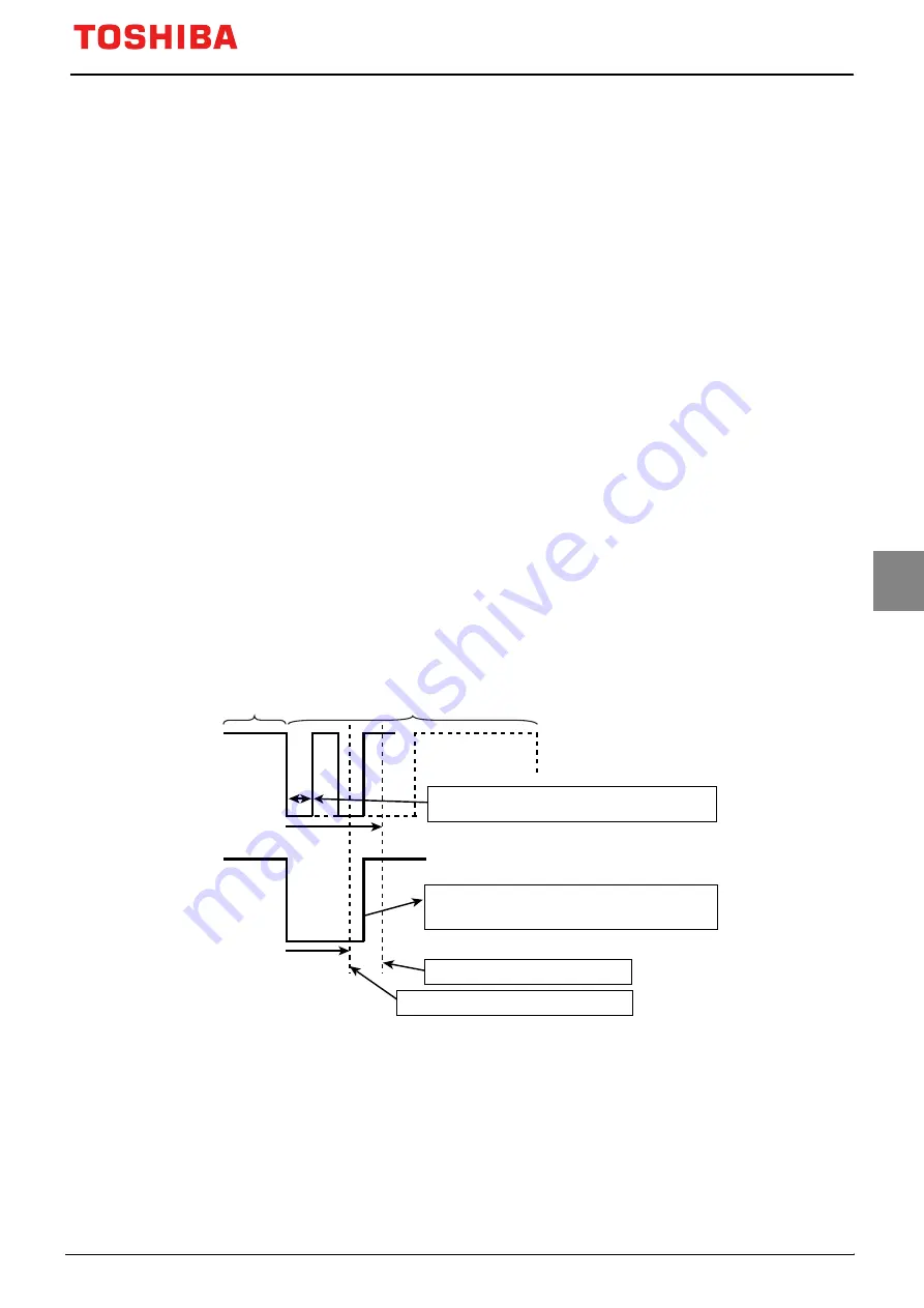
15.4.1.6 Receiving Remote Control Signal without Leader in Waiting Leader
Setting RMCxRCR2 <RMCLD> enables RMC to receive signals with or without a leader.
By setting RMCxRCR2 <RMCLD>, RMC starts receiving data if it recognizes a signal of which
"Low" width is shorter than a maximum "Low" width of leader detection specified in the RMCxRCR1
<RMCLLMAX[7:0]>. RMC keeps receiving data until the final data bit is received.
If RMCxRCR2 <RMCLD> is enabled, the same settings of error detection, reception completion and da-
ta bit determination of 0 or 1 are applied regardless of whether a signal has a leader or not.
Thus receivable remote control signals are limited.
Minimum low width <RMCLLMIN[7:0]>
Maximum data bit cycle <RMCDMAX[7:0]>
RMC starts receiving data by receiving a signal which
is less than the minimum low pulse width.
Waiting for leader
Leader waveform
Maximum data bit cycle is detected if a signal stays
low shorter than specified and longer than a maximum
data bit cycle.
Figure 15-8 Receiving Remote Control Signal without Leader in Waiting Leader (In the case
of RMCxRCR2<RMCLD>="1")
TMPM3V6/M3V4
Page 353
2019-02-06
Содержание TMPM3V4
Страница 1: ...32 Bit RISC Microcontroller TX03 Series TMPM3V6 M3V4 ...
Страница 2: ... 2019 Toshiba Electronic Devices Storage Corporation ...
Страница 7: ...Revision History Date Revision Comment 2019 02 06 1 First Release ...
Страница 8: ......
Страница 22: ...xiv ...
Страница 52: ...TMPM3V6 M3V4 3 Processor Core 3 6 Exclusive access Page 30 2019 02 06 ...
Страница 148: ...TMPM3V6 M3V4 7 Exceptions 7 6 Exception Interrupt Related Registers Page 126 2019 02 06 ...
Страница 178: ...TMPM3V6 M3V4 9 Input Output port 9 2 Block Diagrams of Ports Page 156 2019 02 06 ...
Страница 206: ...TMPM3V6 M3V4 10 16 bit Timer Event Counters TMRB 10 7 Applications using the Capture Function Page 184 2019 02 06 ...
Страница 232: ...TMPM3V6 M3V4 11 Universal Asynchronous Receiver Transmitter Circuit UART 11 4 Operation Description Page 210 2019 02 06 ...
Страница 354: ...TMPM3V6 M3V4 14 Synchronous Serial Port SSP 14 6 Frame Format Page 332 2019 02 06 ...
Страница 419: ...TMPM3V6 M3V4 Page 397 2019 02 06 ...
Страница 420: ...TMPM3V6 M3V4 16 Analog Digital Converter ADC 16 6 Timing chart of AD conversion Page 398 2019 02 06 ...
Страница 462: ...TMPM3V6 M3V4 21 Watchdog Timer WDT 21 5 Control register Page 440 2019 02 06 ...
Страница 510: ...TMPM3V6 M3V4 22 Flash Memory Operation 22 4 Programming in the User Boot Mode Page 488 2019 02 06 ...
Страница 538: ...TMPM3V6 M3V4 25 Electrical Characteristics 25 7 Recommended Oscillation Circuit Page 516 2019 02 06 ...
Страница 541: ...26 3 TMPM3V4FWUG TMPM3V4FSUG Type LQFP64 P 1010 0 50E LPHQVLRQV TMPM3V6 M3V4 Page 519 2019 02 06 ...
Страница 544: ......


