No.
Part to be replaced
Work procedure
Remarks
⑦
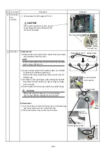
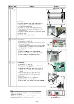
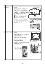
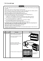
Fan motor, Fan, Fan
case
1. Detachment
1)
2)
Remove the electric parts box cover. (See the 1.of
②
)
Disconnect the connector for the fan motor from the
control board.
CN 333: Motor power supply (3P: White)
3) Remove the clamp
fi
lter from the fan motor leads and
pull the fan motor leads out from the back side of the
electric parts box.
4) Remove the bottom plate of the air inlet.
(See the 1.of
①
)
5) Remove the screws securing the reinforcing plate.
(
Φ
4X8, 2 pcs (screws locate under the cross slit of
heat-insulating material))
Note
Be sure to re-attach the removed clamp
fi
lter to the fan motor leads in the same way
as before replacement.
6) Remove the screws for the fan case (lower) and open
the fan case by pressing the
fi
xing claws on both sides
of the fan case.
7) Remove the earthing screw for the fan motor to
remove the earth wire.
8) Remove the screws ( 5X10, 2 pcs) to secure the
motor band (2 pcs) on the fan motor side.
(The fan motor is temporarily suspended from the
motor base.)
9) While supporting the fan motor with hand, remove the
motor band from the motor base, and remove the fan
motor.
10) Loosen the hexagonal socket screw for the fan,
and pull out the fan from the shaft. (Hex wrench type:
3 mm)
11) Remove the screws (
φ
4X10, 6 pcs) to secure the fan
case (upper), and remove the fan case (upper).
2. Attachment
1) Screw ( 4X10, 6 pcs) to secure the upper fan case to
the same position as before replacement.
2) Insert the fan into the shaft of the fan motor.
Note
Fan motor and fan are directional.
Align the turning direction of the fan blade
with the direction marked on the fan motor
name plate.
3) Secure the fan with the hexagonal socket screw so
that the fan is positioned in the center of the fan case
(upper).
Note
Be sure to use a torque wrench to tighten at
a torque of 4.9N•m or more.
Fan case
fi
xing claws
Fan case
(lower)
Screw C
Screw
Screw
Motor band
Fan blade
Turning direction
Hexagonal socket screw
Reinforcing
plate
Earthing screw
Motor earth wire
Fan motor
connector
position CN333
- 211 -
Содержание MMC-UP0151HP-E
Страница 41: ...2 2 Ceiling type MMC UP0151HP E TR MMC UP0181HP E TR 41 ...
Страница 42: ...MMC UP0241HP E TR MMC UP0271HP E TR 6 4 12 7 42 ...
Страница 43: ...MMC UP0361HP E TR MMC UP0481HP E TR MMC UP0561HP E TR 43 ...
Страница 58: ...3 WIRING DIAGRAMS 3 1 4 way cassette type MMU UP HP E TR 58 ...
Страница 59: ...3 2 Ceiling type MMC UP HP E TR 59 ...
Страница 60: ...3 3 Concealed Duct Standard type MMD UP BHP E TR 60 ...
Страница 61: ...3 4 Concealed Duct High Static Pressure type MMD UP HP E TR 61 ...
Страница 62: ...Concealed Duct High Static Pressure type MMD UP HP E TR 62 ...
Страница 63: ...3 5 Concealed Duct High Static Pressure fresh air intake type MMD UP HFP E TR 63 ...
Страница 65: ...3 7 High wall type MMK UP HP E TR 65 ...
Страница 247: ...MMU UP0241HP E TR MMU UP0271HP E TR MMU UP0301HP E TR 211 233 252 253 251 254 255 213 216 263 247 ...
Страница 249: ...MMU UP0361HP E TR MMU UP0481HP E TR MMU UP0561HP E TR 268 267 213 214 249 ...
Страница 252: ...12 2 Ceiling type MMC UP0151HP E TR MMC UP0181HP E TR 025 024 252 ...
Страница 254: ...MMC UP0241HP E TR MMC UP0271HP E TR 029 028 254 ...
Страница 256: ...MMC UP0361HP E TR MMC UP0481HP E TR MMC UP0561HP E TR 051 028 027 256 ...
Страница 261: ...MMD UP0151BHP E TR MMD UP0181BHP E TR 240 239 238 233 235 261 ...
Страница 263: ...MMD UP0241BHP E TR MMD UP0271BHP E TR MMD UP0301BHP E TR 240 239 238 233 235 263 ...
Страница 265: ...MMD UP0361BHP E TR MMD UP0481BHP E TR MMD UP0561BHP E TR 240 239 238 233 235 265 ...
Страница 289: ...MMK UP0031HPL E TR MMK UP0051HPL E TR MMK UP0071HPL E TR MMK UP0091HPL E TR MMK UP0121HPL E TR 289 ...
Страница 295: ...144 9 MOO 5 BANGKADI INDUSTRIAL PARK TIVANON ROAD TAMBOL BANGKADI AMPHUR MUANG PATHUMTHANI 12000 THAILAND ...


