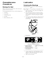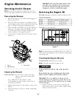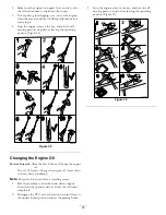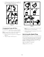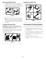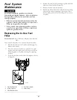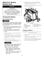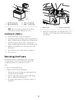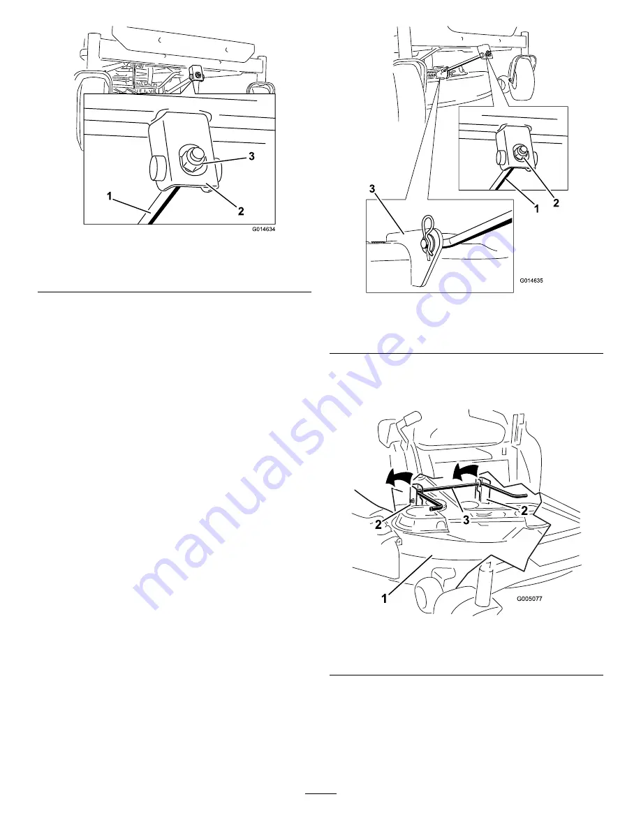
G014634
1
2
3
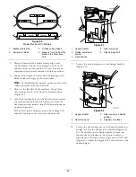
Figure 66
1.
Adjusting rod
3.
Lock nut
2.
Adjusting block
7.
To raise the front of the mower, tighten the adjustment
nut. To lower the front of the mower, loosen the
adjustment nut.
8.
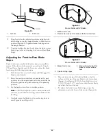
After adjustment, check the front-to-rear slope again.
Continue adjusting the nut until the front blade tip is
1/16-5/16 inch (1.6-7.9 mm) lower than the rear blade
tip (Figure 64 and Figure 65).
9.
When the front-to-rear blade slope is correct check the
side-to-side level of the mower again; refer to Leveling
the Mower from Side-to-Side.
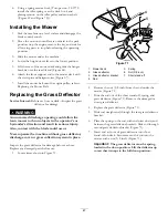
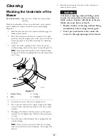
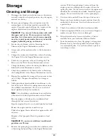
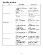
Removing the Mower
1.
Park the machine on a level surface and disengage the
blade control switch.
2.
Move the motion control levers outward to the park
position, stop the engine, remove the key, and wait for
all moving parts to stop before leaving the operating
position.
3.
Lower the height-of-cut lever to the lowest position.
4.
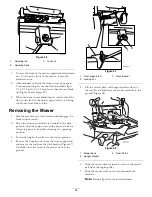
Remove the hairpin cotter from the front support rod
and remove the rod from the deck bracket (Figure 67).
Carefully lower the front of the mower deck to the
ground.
G014635
1
2
3
Figure 67
1.
Front support rod
3.
Deck bracket
2.
Locking nut
5.
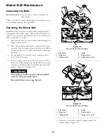
Lift the mower deck and hanger brackets clear of
the rear lift rod and lower the mower carefully to the
ground (Figure 68).
2
2
3
G005077
1
2
2
3
Figure 68
1.
Mower deck
3.
Rear lift rod
2.
Hanger bracket
6.
Slide the mower deck rearward to remove the mower
belt from the engine pulley.
7.
Slide the mower deck out from underneath the
machine.
Note:
Retain all parts for future installation.
45
Содержание TimeCutter ZS 4200
Страница 12: ...121 0772 1 Fast 4 Choke 2 Continuous variable setting 5 Power take off PTO Blade control switch 3 Slow 12 ...
Страница 13: ...121 0773 1 Fast 4 Choke 2 Continuous variable setting 5 Power take off PTO Blade control switch 3 Slow 13 ...
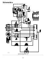
Страница 52: ...Schematics G014644 Electrical Diagram Rev A 52 ...
Страница 53: ...Notes 53 ...
Страница 54: ...Notes 54 ...

