Adjusting the Height of Cut
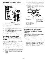
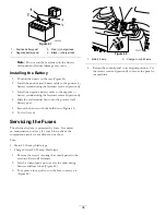
Height-of-cut is controlled by the lever located to the right of
the operating position (Figure 21).
G
015319
1
2
3
Figure 21
1.
Height-of-cut lever
3.
115 mm (4.5 inch),
Transport position
2.
Height-of-cut positions
1.
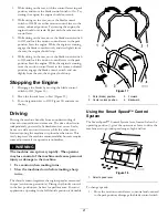
Pull up and inward on the lever to move it to the
desired cutting position.
2.
Once at the desired cutting position, slowly lower the
lever until it engages the position.
The transport position is the highest height-of-cut position or
cutting height
115
inch [4.5 mm] (Figure 21).
Adjusting the Anti-Scalp
Rollers (For 42 inch Mower
Decks)
Whenever you change the height-of-cut, it is recommended
to adjust the height of the anti-scalp rollers.
Note:
Adjust the anti-scalp rollers so the rollers do not touch
the ground in normal, flat mowing areas.
1.
Disengage the blade control switch (PTO), move the
motion control levers to the neutral lock position and
set the parking brake.
2.
Stop the engine, remove the key, and wait for all moving
parts to stop before leaving the operating position.
3.
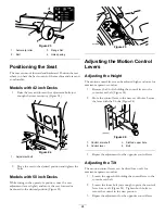
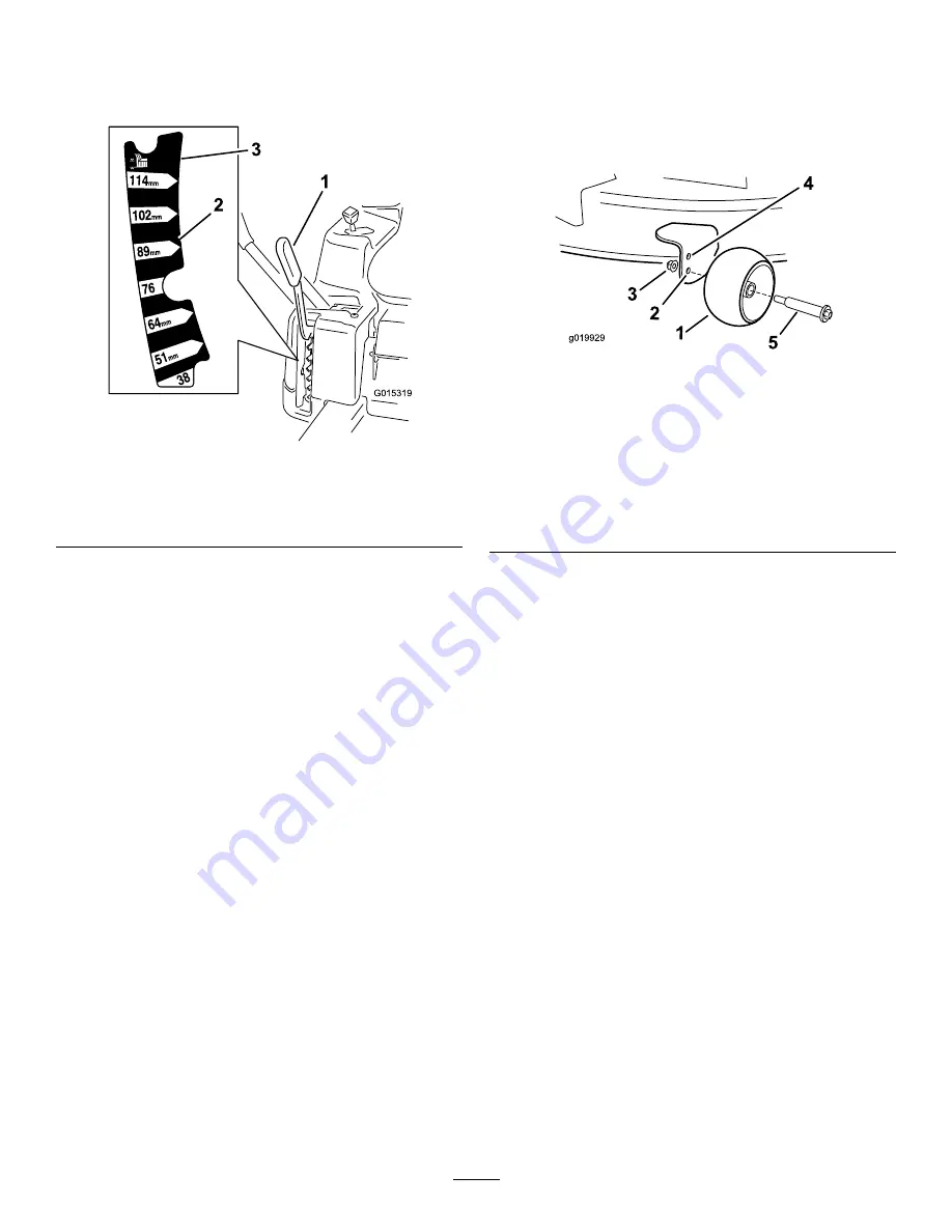
Adjust the anti-scalp rollers to one of the following
positions:
•
Upper hole—use this position with the mower deck
in the 63mm (2-1/2 inch) and below height-of-cut
positions (Figure 22).
•
Lower hole—use this position with the mower
deck in the 76mm (3 inch) and above height-of-cut
positions (Figure 22).
g019929
1
2
3
4
5
Figure 22
1.
Anti-scalp roller
4.
Upper hole—the mower
deck in the 63mm
(2-1/2 inch) and below
height-of-cut positions
2.
Lower hole—the mower
deck in the 76mm (3 inch)
and above height-of-cut
positions
5.
Bolt
3.
Flange Nut
Adjusting the Anti-Scalp
Rollers (For 50 inch Mower
Decks)
Whenever you change the height-of-cut, it is recommended
to adjust the height of the anti-scalp rollers.
Note:
Adjust the anti-scalp rollers so the rollers do not touch
the ground in normal, flat mowing areas.
1.
Disengage the blade control switch (PTO), move the
motion control levers to the neutral lock position and
set the parking brake.
2.
Stop the engine, remove the key, and wait for all moving
parts to stop before leaving the operating position.
3.
Adjust the anti-scalp rollers as shown in Figure 23 to
match the closest height-of-cut position.
23
Содержание TimeCutter ZS 4200
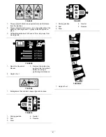
Страница 12: ...121 0772 1 Fast 4 Choke 2 Continuous variable setting 5 Power take off PTO Blade control switch 3 Slow 12 ...
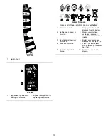
Страница 13: ...121 0773 1 Fast 4 Choke 2 Continuous variable setting 5 Power take off PTO Blade control switch 3 Slow 13 ...
Страница 52: ...Schematics G014644 Electrical Diagram Rev A 52 ...
Страница 53: ...Notes 53 ...
Страница 54: ...Notes 54 ...

