background image

of the sprayer through the InfoCenter in the
Automatic mode.

Note:

An icon for the application rate will appear

in the display of the InfoCenter.

Press the

SPRAYER

-

MODE

switch to the right to

control the application rate of the sprayer by hand
in the Manual mode.

Note:

When switching from the Automatic mode

to the Manual mode, the icon for the application
rate will disappear in the display.

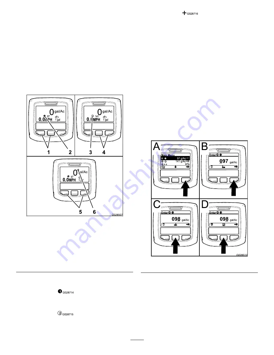
Switching between Sprayer Programming
Settings

g028507

Figure 56

1.

Left and center
buttons—selecting
application rate 1

4.

Center and right
buttons—selecting
application rate 2

2.

Icon—application rate 1

5.

Left and right
buttons—selecting
application rate boost

3.

Icon —application rate 2

6.

Icon —application rate
boost

To select application rate 1, press the left 2 buttons
of the InfoCenter (

Figure 56

).

Note:

An icon

will appear.

To select application rate 2 (application rate),
press the right 2 buttons (

Figure 56

).

Note:

An icon

will appear.

To temporarily apply a boost application rate,
press and hold the 2 outer buttons (

Figure 56

).

Note:

An icon

will appear.

Note:

The application rate boost is an additional

percent above the active program (1 or 2)
application rate. Press and hold the buttons to
apply the boost application rate; release the
buttons to stop the boost rate.

Programming the Application Rate
and Application Rate Boost

HDX-Auto Model

Programming the Application Rate 1 and 2

1.

From the Home screen, press the center
selection button to navigate to the Main Menu.

2.

If needed, press the center selection button to
highlight the application rate for sprayer program
(

Figure 57

).

Note:

The icon for sprayer application rate 1

looks like the numeral 1 in a circle to the right of
a bull's-eye target.

g028512

Figure 57

3.

Press the right selection button to select sprayer
program 1 (A of

Figure 57

).

4.

Set the numerical value by pressing the following
selection buttons:

Press the right selection button (B of

Figure

57

) to move the cursor to the next numerical

position to the right.

Press the center selection button (C of

Figure

57

) to increase the numerical value (0 to 9)

44


Содержание Multi Pro WM 41240

Страница 1: ...i Pro WM requires the installation of one or more interdependent kits Contact your Authorized Toro Dealer for more information Multi Pro WM Turf Sprayer Model No 41240 Serial No 315000001 and Up Regis...

Страница 2: ...nd safely You may contact Toro directly at www Toro com for product safety and operational training materials accessory information help finding a dealer or to register your product Whenever you need...

Страница 3: ...19 Storing the Jack Stands Optional 34 20 Learning More about Your Product 34 Product Overview 36 Controls 36 Specifications 39 Operation 39 Think Safety First 39 Using the InfoCenter 39 Preparing to...

Страница 4: ...erator s Manual of the Workman vehicle Training Material Engine Manual and all labels on the Workman vehicle Be sure to establish your own special procedures and work rules for unusual operating condi...

Страница 5: ...the machine Do not smoke while handling fuel Fill the fuel tank of the machine outdoors Fill the fuel tank of the machine to about 25 mm 1 inch below the top of the tank the bottom of the filler neck...

Страница 6: ...Keep foot off accelerator pedal Turn ignition key to Start Using the machine demands attention Failure to operate vehicle safely may result in an accident tip over of vehicle and serious injury or dea...

Страница 7: ...ry Do not accelerate quickly or slam on the brakes when backing down a hill especially with a load Never drive across a steep hill always drive straight up or down or go around the hill If the engine...

Страница 8: ...must be relieved by stopping engine cycling dump valve from raise to lower and or lowering the tank and attachments If the tank must be in the raised position secure it with the safety support To mak...

Страница 9: ...ntrol 2 Manual open loop rate control decal120 0616 120 0616 1 Warning read the Operator s Manual use fresh clean water for first aid washing decal120 0622 120 0622 1 Warning read the Operator s Manua...

Страница 10: ...ne decal125 4052 125 4052 1 Raise left boom 4 Lower right boom 2 Lower left boom 5 Toggle tank rinse on off 3 Raise right boom 6 Toggle sonic boom on off decal125 8139 125 8139 1 Toggle boom sprayers...

Страница 11: ...d overhead power lines check the area for overhead power lines before operating the machine in the area decal127 3937 127 3937 1 Warning do not step 3 Entanglement hazard belt keep away from moving pa...

Страница 12: ...4 1 Left boom 5 Center boom spray on 9 Right boom spray off 13 Agitation 2 Left boom spray on 6 Center boom spray off 10 Speed 14 Agitation on 3 Left boom spray off 7 Right boom 11 Increase speed 15 A...

Страница 13: ...m section Console mounting bracket 1 Flange locknut 5 16 inch 3 Flange head bolt 5 16 inch 3 3 Plastic bushing 2 Install the console mounting bracket 4 Hold down brackets 2 Install the attachment hold...

Страница 14: ...ater tank 1 Fresh water tank mount 1 Flanged locknut 5 16 inch 2 Washer 5 16 inch 2 Flanged head bolt 5 16 x 2 1 4 inch 2 16 Flanged head bolt 5 16 x 5 8 inch 4 Install the fresh water tank Fill recep...

Страница 15: ...er and shut off the engine refer to the Operator s Manual of your machine 4 Remove the lynch pins from the outer ends of the cylinder rod clevis pins Figure 3 g002368 Figure 3 1 Cylinder rod end 4 Lyn...

Страница 16: ...Model Fully install the High Flow Hydraulics Kit for Workman HDX Auto Utility Vehicles refer to the Installation Instructions for the High Flow Hydraulics Kit Workman HDX Auto Utility Vehicle Lifting...

Страница 17: ...he bracket for the optional hand throttle kit is mounted If the hand throttle kit is installed you will need to remove the bracket of the hand throttle assembly from the dashboard align the control mo...

Страница 18: ...e 4 Engine support tube 2 Flanged locknut 5 Lift cylinder 3 Flanged head bolt 2 Rotate the lift cylinder to provide clearance to install the hold down bracket for the tank skid Figure 8 3 Assemble the...

Страница 19: ...igure 10 1 Rear lift point 2 Front lift point 2 Position the drain valve as follows A At the left side of the tank loosen the 2 flanged head bolts that secure the drain valve to the valve support brac...

Страница 20: ...d support onto the cylinder rod making sure that the support end tabs rest on the end of cylinder barrel and on the cylinder rod end Figure 15 g009164 Figure 15 1 Bed support 3 Skid frame 2 Lift cylin...

Страница 21: ...re 17 7 Coupling the Sprayer Pump No Parts Required Procedure For HD series models with a manual transmission couple the PTO shaft to the transaxle PTO refer to the Installation Instructions for the M...

Страница 22: ...cated in Figure 19 or Figure 20 using the existing screws g002507 Figure 19 HD Series models with an manual transmission 1 J clip 3 Control box harness 2 Existing screws 4 Center console g028443 Figur...

Страница 23: ...of the open yellow power wire of the fuse block for the machine and the insulated blade terminal at the end of the yellow optional power wire of the fuse block of the sprayer wiring Figure 23 g028444...

Страница 24: ...sprayer 7 Attach the fuse decal on a surface nearby the fuse block for the sprayer 10 Connecting the Sprayer Harness to the Battery Parts needed for this procedure 1 Battery terminal bolt 2 Clamp nut...

Страница 25: ...tighten the clamp nut to 1978 to 2542 N cm 175 to 225 in lb 7 Slide the cover over the for the positive battery terminals 8 Squeeze the sides of the battery cover and insert tabs into the slots in the...

Страница 26: ...ort cradle 4 Bolt 1 2 x 1 1 4 inches 4 Flange nut 1 2 inch Assembling the Boom Transport Cradles 1 Attach lifting equipment to the center boom section and remove it from the shipping container 2 Align...

Страница 27: ...icle For HDX Auto Model refer to the installation instructions for the Multi Pro WM Turf Sprayer Finishing Kit Automatic Workman Utility Vehicle 13 Installing the Left and Right Boom Section Parts nee...

Страница 28: ...ign the rod end of the boom lift cylinder with the holes in the horn of the pivot bracket Figure 30 g028738 Figure 31 1 Rod end boom lift cylinder 3 Clevis pin 5 8 x 4 3 4 inch 2 Horn pivot bracket 4...

Страница 29: ...ulder bolt 2 Washer 2 Nut Installing the Left and Right Boom Section Hoses 1 Route the boom section hoses as shown in Figure 32 and Figure 33 g028468 Figure 32 Hose Left Boom Segment 1 Nut 4 Shoulder...

Страница 30: ...the boom section hose over the barbed T fitting at the boom section and secure the hose with a hose clamp Figure 32 and Figure 33 Note Apply a coat of liquid soap to the hose barb of the tee fitting...

Страница 31: ...de the nozzle receptacle over the nozzle fitting on a turret 3 Turn the nozzle clockwise to lock the cams on the receptacle in place 4 Verify the fan portion of the nozzle See the Installation Instruc...

Страница 32: ...h 3 Mount fresh water tank 2 Secure the mount to the tube Figure 36 with 2 flanged head bolts 5 16 x 2 1 4 inch 2 washers 5 16 inch and 2 flanged locknuts 5 16 inch 3 Torque the bolts and nuts to 1978...

Страница 33: ...s the springs to 4 cm 1 1 2 inches if necessary The sprayer is shipped with the boom extensions swung forward to facilitate packaging of the machine The springs are not fully tightened at the time of...

Страница 34: ...2 inch 2 Clevis pin 3 inch 2 Knob Procedure 1 Insert the front jack stands upside down into the frame near the front tie down points Figure 40 g023740 Figure 40 1 Front jack stand 2 Knob 2 Secure the...

Страница 35: ...ing material 1 Parts Catalog 1 Registration card 1 Selection guide 1 Pre delivery inspection sheet Procedure 1 Read the manuals 2 View the operator training material 3 Use the nozzle selection guide t...

Страница 36: ...m lift switches 8 Application rate switch 4 InfoCenter 9 Agitation switch 5 Pressure gauge Controls InfoCenter LCD Display The InfoCenter LCD display shows information about your machine and battery p...

Страница 37: ...ward to decrease application rate Boom Lift Switches The electric BOOM LIFT switches raise and lower their respective booms Figure 42 There is a left and right lift switch Press and hold the switch up...

Страница 38: ...ss valve 3 Right boom section bypass valve 2 Center boom section bypass valve Agitation Throttle Valve This valve is located on the rear left side of the tank Figure 46 Turn the knob on the valve to t...

Страница 39: ...on a trailer with the sprayer installed make sure the booms are tied down and secure Think Safety First Please carefully read all of the safety instructions and decals in the safety section Knowing th...

Страница 40: ...selection button Total area sprayed A of Figure 51 Right selection button Application rate B of Figure 51 Left selection button Sub area sprayed C of Figure 51 Left selection button Tank volume D of...

Страница 41: ...e Pressing the left selection button will save your selection exit the Settings menu and return to the Main Menu 3 To change the language used in the display pressing the center selection button the b...

Страница 42: ...t menu and return to the Settings menu Figure 54 6 To adjust the contrast level of the display press the center selection button the button below the down arrow icon in the display to move the selecte...

Страница 43: ...ccess the calibration settings in the InfoCenter menu system by pressing the menu access button while at the main screen This will bring you to the main menu Refer to the following tables for a summar...

Страница 44: ...mporarily apply a boost application rate press and hold the 2 outer buttons Figure 56 Note An icon will appear Note The application rate boost is an additional percent above the active program 1 or 2...

Страница 45: ...n rate boost Figure 58 Note The icon for the the application rate boost look 2 signs to the right of a bull s eye target Figure 58 g028513 Figure 58 3 Press the right selection button Figure 58 to inc...

Страница 46: ...s set press the right selection button Note The checkmark icon will appear above the center selection button D of Figure 61 6 Press the center selection button D of Figure 61 to enter the password Cha...

Страница 47: ...button Note The sub menus for L Boom C Boom R Boom and Reset Defaults will appear 7 Press the center selection button to highlight the Protect Settings entry 8 Press the right selection button Note A...

Страница 48: ...ng with the retainer that you removed in step 2 Inspecting the Tank Straps Service Interval Before each use or daily Check the tank straps Important Over tightening the tank strap fasteners can result...

Страница 49: ...the passenger seat Figure 69 It supplies a source of fresh water for you to wash chemicals off of your skin eyes or other surfaces in case of accidental exposure To fill the tank unscrew the cap on th...

Страница 50: ...the hydraulic lift lock left to engage the lock Figure 70 or Figure 71 Changing the Boom Position 1 Stop the sprayer on level ground 2 Use the BOOM LIFT switches to lower the booms Note Wait until the...

Страница 51: ...late the APPLICATION RATE switch until the monitor displays the desired application rate Note HD series models with a automatic transmission that are operated in the automatic mode the computer will a...

Страница 52: ...a level surface stop the engine and set the parking brake 2 Set the master BOOM SWITCH to the Off position and then set the PUMP switch to the Off position 3 Remove the clogged nozzle and clean it usi...

Страница 53: ...tside of the sprayer with clean water 17 Remove the nozzles and clean them by hand Replace damaged or worn nozzles Calibrating the Sprayer Preparing the Machine for Calibration Important Before calibr...

Страница 54: ...UPERVISOR RATE LOCKOUT switch to the Lock position 10 Turn off the MASTER BOOM switch 11 On the InfoCenter navigate to the Calibration menu and select Flow Calibration as follows Note Selecting the Ho...

Страница 55: ...ransmission as follows For HD Series Models with a manual transmission shift the transmission to Neutral For the HDX Auto model shift the transmission to P park 3 Set the parking brake and turn the en...

Страница 56: ...ayer tank is filled with water 2 Verify the agitation control valve is open If it has been adjusted open it completely at this time 3 Set the transmission as follows For HD Series Models with a manual...

Страница 57: ...smission to P park 4 Set the PUMP switch to the On position 5 Set the AGITATION switch to the On position 6 Set the MASTER BOOM switch to the Off position 7 Set the engine speed as follows For machine...

Страница 58: ...te the pump Every 100 hours Lubricate the grease fittings Lubricate the boom hinges Every 200 hours Inspect all hoses and connections for damage and proper attachment Clean the flowmeter More often wh...

Страница 59: ...nspect the air filter before filling the tank Inspect the engine cooling fins before filling the tank Check any unusual engine noises Check any unusual operating noises Check the tire pressure Check f...

Страница 60: ...ised up to allow full access to the engine and other internal components Pivot the boom extension forward to distribute the weight more evenly Use the following procedure 1 Park the vehicle with an em...

Страница 61: ...ers to secure the tank assembly 4 Fold the boom extensions rearward to the extended position 5 Use the BOOM CONTROL switches to raise the boom extensions to the transport position Lubrication Greasing...

Страница 62: ...f according to the chemical manufacturer s recommendations For example use appropriate Personal Protective Equipment PPE including face and eye protection gloves or other equipment to guard against pe...

Страница 63: ...82 Note Ensure that the filter element is firmly seated into the filter head 8 Install the bowl onto the filter head hand tight Figure 82 9 Install the plug into the bowl hand tight Figure 82 Inspecti...

Страница 64: ...t tightened to lock new position 4 Jam nut loosened 6 Turn the eyelet rod in the actuator rod to shorten or lengthen the extended actuator to the desired position Figure 84 Note You must turn the eyel...

Страница 65: ...pivot pin and secure it with the bolt and nut removed previously Repeat this procedure for each boom Cleaning Cleaning the Flowmeter Service Interval Every 200 hours Yearly whichever comes first More...

Страница 66: ...73 6 Installing the Valve Actuator page 75 To clean the 3 section valves refer to the following sections 1 Removing the Valve Actuator page 66 2 Removing the Section Manifold Valve page 69 3 Cleaning...

Страница 67: ...anged head bolt 4 Retainer 2 Valve mount 5 Socket outlet fitting 3 Flanged locknut 6 Manifold valve assembly 3 Remove the 2 flanged head bolts and 2 flanged locknuts that secure the rate control valve...

Страница 68: ...Boom Manifold Valve 1 Remove clamps and gaskets that secure the manifold for the master boom valve Figure 92 to the master boom bypass valve agitation valve and 90 flanged elbow at the end of the hose...

Страница 69: ...Flange clamp 3 Flange adjacent section valve 2 Remove the retainers that secure the outlet fitting to the section valve manifold and the valve manifold to the bypass fitting Figure 95 g028238 Figure...

Страница 70: ...alve closed 2 Remove the 2 endcap fitting assembies from each end of the manifold body Figure 98 and Figure 99 g028243 Figure 98 Agitation Valve Manifold 1 Stem retainer 7 Back seating O ring 0 676 in...

Страница 71: ...et fitting O rings section valve manifold only endcap O rings back seating O rings ball seat for damage or wear Figure 98 and Figure 99 Note Replace any damaged or worn O rings or seats 2 Apply grease...

Страница 72: ...sket and agitation valve manifold with a clamp and tighten by hand A of Figure 101 5 Assemble the rate control valve to the valve mount with the 2 flanged head bolts and 2 flanged locknuts A of Figure...

Страница 73: ...en by hand B of Figure 102 7 Align a gasket between the flanges of the agitation valve manifold and the adapter fitting for the agitation throttle valve C of Figure 102 8 Assemble the agitation valve...

Страница 74: ...reducer coupling 6 Socket outlet fitting 2 Socket bypass fitting 7 Retainer 3 Bypass fitting 8 Flange manifold section valve 4 Flange adjacent manifold agitation valve 9 Gasket 5 Endcap fitting manifo...

Страница 75: ...ve use of water especially near the control panel lights engine and the battery 3 Condition the sprayer system as follows A Drain the fresh water tank B Drain the spray system as completely as possibl...

Страница 76: ...9 Installing the Sprayer Fuse Block page 22 3 Remove the wiring harness from J clips refer to 8 Installing the Control Console and Electrical Harness page 21 4 Loosen the hand knob that is located bel...

Страница 77: ...disconnect the PTO shaft from the transaxle PTO refer to the installation instructions for the Multi Pro WM Turf Sprayer Finishing Kit Manual Workman Utility Vehicle For HDX Workman with a automatic...

Страница 78: ...stem is damaged 6 Contact your Authorized Service Dealer A boom section does not turn off 1 The boom section valve is damaged 1 Disassemble the boom section valve refer to the section Cleaning the Spr...

Страница 79: ...Schematics g255886 Flow Diagram Sprayer System DWG 125 0699 Rev B 79...

Страница 80: ...Notes...

Страница 81: ...Notes...

Страница 82: ...Notes...

Страница 83: ...3766 3636 Jean Heybroek b v Netherlands 31 30 639 4611 Victus Emak Poland 48 61 823 8369 European Privacy Notice The Information Toro Collects Toro Warranty Company Toro respects your privacy In order...

Страница 84: ...ot limited to damage to seats due to wear or abrasion worn painted surfaces scratched decals or windows etc Parts Parts scheduled for replacement as required maintenance are warranted for the period o...

Отзывы: