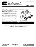


Figure 29
1.
Turn-signal switch
2.
8-socket connector
Routing the Wire Harness to the Horn
1.
Route the wire harness through the grommet at the
hole in the rear-angle platform to the horn (
Figure 30
1.
Horn
2.
Grommet at the hole
2.
Connect the wire-harness leg with the 2 terminals to
the 2 terminals on the horn (
Note:
Rotate the horn as needed to connect the
terminals for the wire harness.
Figure 31
1.
Horn
3.
Terminal of the
wire-harness leg
2.
Terminal of the horn
3.
Tighten by hand the nut that secures the horn to the
90° bracket; refer to
in
(page 11)
.
Routing the Wire Harness to the
Headlights
1.
Route the wire harness along the hoses in the floor-pan
opening (
).
Figure 32
1.
Floor-pan opening
3.
Hoses
2.
Wire harness
2.
Route the short leg of the wire harness to the right
headlight.
3.
Route the long leg of the wire harness to the left
headlight.
4.
Connect the 6-socket connector of the wire harness to
the 6-pin connector of the right headlight (
).
15