23
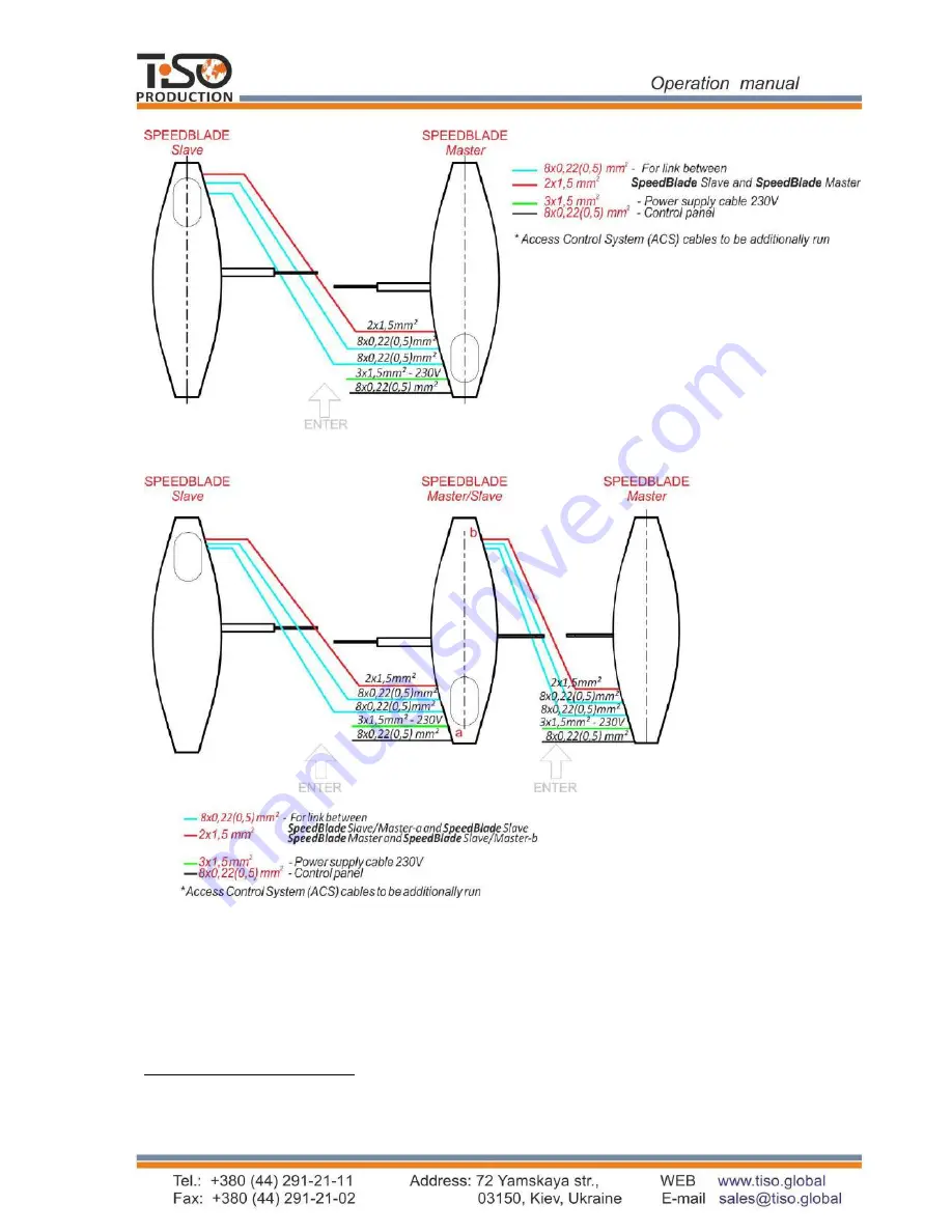
Fig. 12
–
Cable entries between the turnstile
†
Master
(«
SpeedBlade
»
-1 )
pedestal
Slave
-1)-
Master/Slave
-2 )
double blade pedestal
Страница 1: ...TiSO PRODUCTION LTD WAIST HIGH TURNSTILE SpeedBlade 3 D V X OPERATION MANUAL AUIA177 OM 2018...
Страница 2: ...malfunctions 29 4 2 Possible malfunctions 29 4 3 SpeedBlade turnstile blade initialization procedure 30 4 3 Postrepair checkout 32 5 TRANSPORTATION AND STORAGE 32 5 1 Turnstile storage 32 5 2 Turnsti...
Страница 3: ...stile includes two pedestals left hand and right hand each of which has one telescopic glass blade The turnstile row is provided by installation one more or a number of additional pedestals equipped w...
Страница 4: ...hould be connected to AC network with parameters specified in p 1 2 Specifications inspection adjustment and repair should be performed only after the turnstile is deenergized After the turnstile is p...
Страница 5: ...imensions mm Maximum weight kg L Single Double 3 D PV 1 1000 1000 1480 233 3 D SV 1 3 D KV 1 3 D PV 2 2270 339 3 D SV 2 3 D KV 2 When the turnstile with more than two access ways is ordered B 900 290...
Страница 6: ...ition Vertical deviation from vertical position no more than 1 to any side is tolerated 1 1 5 Reliability indices mean time to repair without delivery time of spare parts tools and accessories at most...
Страница 7: ...or more additional pedestal with two blades reference designation 3 D V Arrangement of access ways through the turnstile 3 D V 2 is shown in Figure 2 one access way 3 D V 1 b two access ways 3 D V 2 F...
Страница 8: ...t hand and right hand and one additional pedestal with two retractable glass blades The body of additional pedestal includes frame base set of side panels and doors top lid two actuators with glass bl...
Страница 9: ...ushed stainless steel or polished stainless steel 1 3 6 Turnstile scope of delivery The turnstile is delivered in set a kit of pedestals depending on the number of access ways The turnstile is deliver...
Страница 10: ...of stainless steel side panels 8 9 and door 10 See Fig 4 bottoms of which are rigidly fixed to the base 5 and on the top they are fixed to the frame upper plate 11 Frame is a set of brackets and posts...
Страница 11: ...the turnstile body the panels are fixed on which controllers power supply unit battery and terminal blocks to be connected to 230V mains and control devices are located Controllers 201 01 00 00 contr...
Страница 12: ...NGLE ACCESS IN THE DIRECTION SINGLE ACCESS IN THE DIRECTION B SINGLE ACCESS IN BOTH DIRECTIONS FREE ACCESS IN THE DIRECTION FREE ACCESS IN THE DIRECTION B FREE ACCESS IN BOTH DIRECTIONS LOCK OF ACCESS...
Страница 13: ...is traced and the signal DETECTION OF ACCESS of 0 3 second duration is generated to the relevant output OUT3 or OUT4 In this state the turnstile will be until arrival of command CANCELLATION OF FREE...
Страница 14: ...no obstacles in the closing area The turnstile will return to the mode preceding the ALARM mode as soon as causes of this mode disappear In this case the output OUT5 will go to passive state siren al...
Страница 15: ...rface RS 485 5 4 GND COMMON WIRE 1 1 BUZ Output for connection of audible alarm The output is active in case of unauthorized access 1 type of output open collector 2 peak voltage on privacy key 60V 3...
Страница 16: ...t sensor Control commands come to inputs IN1 and IN2 from the controller AUIA 206 21 20 00 Table 6 Connector contact Descriptio n Direction Designation Signal description and parameters X1 1 IN1 ENTRY...
Страница 17: ...e 1 type of output open collector 2 peak voltage on privacy key 50V 3 peak current of public key 5A X2 6 MG1 EXIT Not applicable X2 7 MG2 EXIT Not applicable X2 8 MG2 EXIT Not applicable X2 9 MOT1 EXI...
Страница 18: ...n time of the turnstile access in single access mode equals to 2 sec Escape door portal or pedestrian gate can be installed near the turnstile to increase the turnstile traffic flow capacity in case o...
Страница 19: ...to be used Fig 8 puncher concrete drills according to diameter of anchors included in the turnstile scope of delivery extension cord kit of end and pin wrenches kit of hexagons kit of screwdrivers ha...
Страница 20: ...r defects and damages as well as completeness to be checked according to the turnstile data sheet WARNING When the turnstile damages are detected or in case of shortage of delivery installation work t...
Страница 21: ...is ready as follows The site surface to be flat and horizontal Thickness of concrete blinding coat under the site to be at least 150 mm WARNING The turnstile is fixed by means of Redibolt with jacket...
Страница 22: ...rking due to diameter of anchors 12 120 10 for the turnstile fixation 7 Anchor jackets to be inserted into the prepared holes WARNING The turnstile installation and fixation to be performed only after...
Страница 23: ...23 Fig 12 Cable entries between the turnstile Master SpeedBlade 1 pedestal Slave SpeedBlade 1 pedestal Master Slave SpeedBlade 2 double blade pedestal...
Страница 24: ...available access holes in the turnstile post bottom end part by reclining the turnstile 13 Fixation holes at the turnstile bottom plate to be aligned with prepared surface holes 14 The turnstile to be...
Страница 25: ...The turnstile door and side pieces Fig 17 to be installed at their fixation locations and table board to be fixed with screws Fig 17 Body installation on the turnstile frame 16 Installation of proximi...
Страница 26: ...1 When the turnstile is commissioned it is necessary to perform inspections specified in Table 7 During inspections the wiring diagram according to Annex C and the control panel according to Appendix...
Страница 27: ...cess in opposite direction FREE button to be pushed for access in chosen direction A or B and LOCK button to be pushed for locking access in opposite direction Green arrow of authorized free access in...
Страница 28: ...vant safety measures according to p 2 1 to be observed IT IS FORBIDDEN TO USE DEFECTIVE APPLIANCES TOOLS FUSES INSTRUMENTATION THE SERVICE LIFE OF WHICH HAS EXPIRED 3 2 2 When instrumentations are pre...
Страница 29: ...anual control in the modes specified in Table 7 or when identification cards are used verification of reliability of the turnstile screw joints and earthing connections 4 ROUTINE MAINTENANCE 4 1 Possi...
Страница 30: ...to be checked Blade remains open Magnetic sensor is out of order Mechanism jamming FREE ACCESS mode is set Infrared sensors are out of order Blade opening to be checked manually turning off power sup...
Страница 31: ...s MOT1 10 The turnstile to be energized 11 Turnstile operation to be checked 12 New zero position setting is completed Magnetic sensor and magnet gap control Normal gap is 1mm If LED is lit then gap i...
Страница 32: ...install turnstile to be transported according to the transportation regulations related to the relevant mode of transport such as in railway or special containers in closed vehicles waterborne in shi...
Страница 33: ...OM preventing further use of the turnstile 7 4 The Manufacturer does not bear responsibility and warranty liabilities for the turnstile damage due to nonobservance of the requirements specified by thi...
Страница 34: ...European Standards EN 60335 1 2002 EN 61000 6 1 2007 EN 61000 6 3 2007 EN 61000 4 2 2009 EN 61000 4 3 2006 EN 61000 4 4 2004 EN 61000 4 5 2006 EN 61000 4 11 2004 and is in conformity with requirement...
Страница 35: ...Annex mandatory Overall and installation dimensions of the SpeedBlade type turnstile T3 KCD XV 1 Fig 1 Single turnstile right hand and left hand pedestal Master and Slave...
Страница 36: ...ntinued Annex Overall and installation dimensions of the SpeedBlade type turnstile T3 KCD XV 2 Fig 2 Double turnstile right hand right hand left hand and left hand pedestal Master Master Slave and Sla...
Страница 37: ...ontrol panel body 5 FREE ACCESS mode control button 2 SINGLE ACCESS mode control button 6 PANIC mode control button 3 front plate 7 access direction LED display 4 LOCK mode control button 8 controller...
Страница 38: ...38 Continued Annex B Control panel and connection diagram Fig B 2 Connection diagram of control panel AUIA 114 02 00 00...
Страница 39: ...6 3 XP2 10 8 7 5 4 2 1 GND POW XT5 IN 5 IN 2 OUT5 OUT4 OUT2 OUT1 XT3 GND 12V 12V 2 2 1 2 4 3 XP4 1 8 7 4 5 2 1 9 6 3 XP1 IN 6 IN 3 GND IN 4 XT4 IN 1 OUT3 GND XT2 RED 2 12V 12V AUX2 AUX1 IR OUT8 IR OUT...
Страница 40: ...command is issued the input is activated for 5 sec inp2 TO BE OPENED B in pulse mode When command is issued the input is activated for 5 seconds 3 PANIC inp GND of power supply common wire out3 DETEC...
Страница 41: ...n pulse mode When command is issued the input is activated for 5 sec inp2 TO BE OPENED B in pulse mode When command is issued the input is activated for 5 seconds inp3 PANIC GND of power supply common...
Страница 42: ...se mode When command is issued the input is activated for 5 sec inp2 TO BE OPENED B in pulse mode When command is issued the input is activated for 5 seconds inp3 PANIC GND of power supply common wire...
Страница 43: ...43 Annex D 4 mandatory Diagram of the turnstile connection to control panel 5 4 3 2 1 P B A G...