2-19
2
TANDEM PUMP REPLACEMENT 2.10
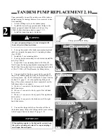
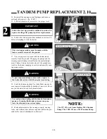
10 Connect the tandem pump case drain fitting and
hose. Torque the fittings and hoses to the specifications
listed in the Torque Chart in Section 2.13 page 2 - 53.
C1882
Case drain connection
C4259
To control valve
11 Connect the auxiliary gear pump outlet fittings and
hoses to the gear pump. (fig. C4259) Follow the Torque
Chart in Section 2.13 page 2 - 53 when tightening fit-
tings and hoses.
12 Connect the inlet fitting and hose to the auxiliary
gear pump. (fig. C4259a) Torque the fittings and hoses to
the specifications listed in the Torque Chart Section 2.13.
C4259a
C2072
Charge line
IMPORTANT
When making repairs to the hydraulic system, keep
the work area and parts clean. Use caps and plugs
on all open line and ports.
IMPORTANT
Inspect fitting o-rings and flares for marks or dam-
age. Replace if necessary.
IMPORTANT
Follow the Torque Chart In Section 2.13 when tight-
ening fittings and hoses.
Gear pump
Gear pump
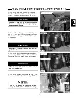
From the reservoir
13 Connect the charge pressure outlet line from the tan-
dem pump to the hydraulic brake valve. (fig. C2072)
Brake valve
NOTE:
NOTE:
The 137 / 153 use a Sauer Danfoss M44Tandem
Pump. The 1300 /135 use a M35 Tandem Pump.
Содержание 1300 ProTough
Страница 1: ...REPAIR MANUAL 135 137 153 1300 ProTough Publication No 49702 September 2004 THOMAS...
Страница 13: ...1 HYDRAULIC SCHEMATIC 1 1 1 3 C4475...
Страница 61: ...1 1 51 NOTES...
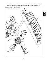
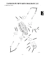
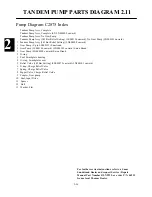
Страница 86: ...2 25 2 TANDEM PUMP PARTS DIAGRAM 2 11 C 2875 6 1 5 5 2 7 8 10 11 12 13 4 4 4 4 3 3 9 2 LN000500 onward shown...

