2-18
2
TANDEM PUMP REPLACEMENT 2.10
IMPORTANT
When making repairs to the hydraulic system, keep
the work area and parts clean. Use caps and plugs
on all open line and ports.
Upon reassembly, inspect the outside area of the tandem
pump housing for damage that may have occurred in tran-
sit or handling.
1
Attach a lifting device to the tandem pump.
2
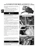
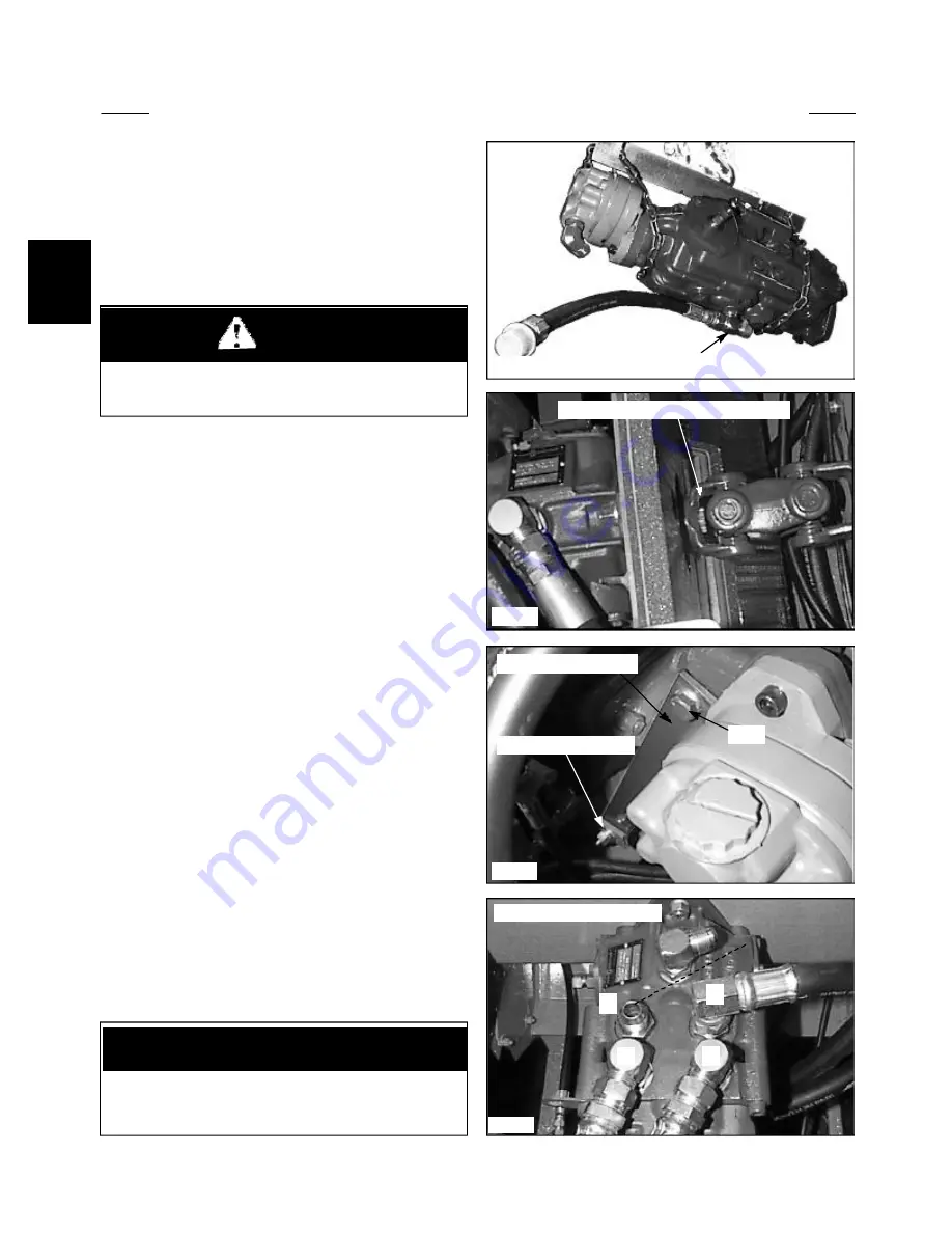
Install the lower charge pressure inlet fitting to the
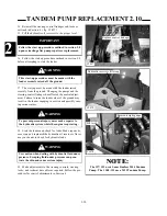
tandem pump and attach the brake valve hose. (fig.
C2069) Follow the torque chart on page 2 - 53.
3
Install the tandem pump to the loader.
C2068
Bolt
Lower mounting bolt
C2071
1
4
3
2
C2069
C2070
8
Connecting the 4 high pressure drive hoses and fit-
tings to the tandem pump can only be accomplished in a
certain sequence. (fig. C2071) Follow the Torque Chart in
Section 2.13, page 2 - 53 when tightening fittings and
hoses. If you have removed the hoses completely use the
following pattern to reconnect:
A
Hose no. 1 connects to the bottom port of the left
hand drive motor.
B
Hose no. 2 connects to the top port of the left hand
drive motor.
C
Hose no. 3 connects to the top port of the right hand
drive motor.
D. Hose no. 4 connects to the bottom port of the right
hand drive motor.
4
Line up the u-joint to the tandem pump input splined
shaft as you guide the pump into it’s mounting location.
( fig. C2070)
5
Install the 2 rear mounting bolts.
6
Line up the front mounting brace holes and install the
bolt. (fig. C2068)
7
Torque the 2 rear mounting bolts to 60 ft lbs. (82
Nm) Torque the front pump bracket mounting bolt to 50ft
lbs (68 Nm) Torque the front lower mounting bracket bolt
at 20 to 25 ft lbs. (32 Nm) Remove the lifting device.
9
Connect the charge inlet hose from the oil filter to
the tandem pump. Torque the fittings and hoses according
to the Torque Chart in Section 2.13 page 2 - 53.
Charge pressure inlet fitting
WARNING
To prevent personal injury, do not attempt to lift
heavy objects without assistance.
High pressure hose layout
Front mounting brace
Line up pump spline to u-joint yoke
Содержание 1300 ProTough
Страница 1: ...REPAIR MANUAL 135 137 153 1300 ProTough Publication No 49702 September 2004 THOMAS...
Страница 13: ...1 HYDRAULIC SCHEMATIC 1 1 1 3 C4475...
Страница 61: ...1 1 51 NOTES...
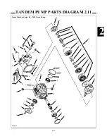
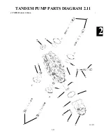
Страница 86: ...2 25 2 TANDEM PUMP PARTS DIAGRAM 2 11 C 2875 6 1 5 5 2 7 8 10 11 12 13 4 4 4 4 3 3 9 2 LN000500 onward shown...


