1
1-46
HYDRAULIC OIL RESERVOIR 1.7
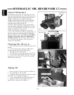
The hydraulic oil reservoir is located at the rear of the
loader on the left hand side. (fig. C4214) The reservoir is
completely separated from all chain and gear drives to
eliminate contamination. A magnetic drain plug is
installed in the bottom of the reservoir, and a magnet is
attached to the 100 micron suction filter, to assist in
removing metal particles from the oil.
Oil level is checked through a site gauge located just
inside the engine compartment, left hand side, on the oil
reservoir. The proper fill level is marked by a line and
should be checked daily. (fig. C1878)
The oil reservoir fill cap is located at the top of the
reservoir. (fig. C1879) The oil fill cap assembly has a 30
micron screen to catch larger particles of contaminant
before entering the reservoir, but
always use oil filtered
through a 5 micron min. filter for replenishing the
hydraulic reservoir.
The oil fill cap is also a reservoir
vent, or breather, and contains a 10 micron filter to
remove air borne particles.
General Information
Checking The Oil Level
1
Check the reservoir oil level with the loader on level
ground.
2
Lower the boom arms, retract the cylinders and
engage the parking brake. Shut off the engine.
3
Open the rear door. (fig. C4223)
4
Check the oil level in the sight gauge. (fig. C1878)
5
If oil is visible approximately mid way in the sight
gauge, the level is correct. The correct level is marked
with a line from the factory.
Adding Oil
1
Remove the bolt, or lock, on the reservoir filler cap.
2
Open the filler cap. (fig. C1879)
3
Inspect the filler screen in the filler neck for damage.
If the filler screen is damaged, replace it.
4
Using a clean container, add 10W30 API class SJ.
5
Replace the filler cap and replace the bolt, or
padlock, in the cap to prevent vandalism.
C4214
Hydraulic oil
reservoir
C1879
Reservoir filler cap
C1878
Reservoir sight gauge
Oil level
C4223
Open rear door
Bolt
Содержание 1300 ProTough
Страница 1: ...REPAIR MANUAL 135 137 153 1300 ProTough Publication No 49702 September 2004 THOMAS...
Страница 13: ...1 HYDRAULIC SCHEMATIC 1 1 1 3 C4475...
Страница 61: ...1 1 51 NOTES...
Страница 86: ...2 25 2 TANDEM PUMP PARTS DIAGRAM 2 11 C 2875 6 1 5 5 2 7 8 10 11 12 13 4 4 4 4 3 3 9 2 LN000500 onward shown...


