2-42
2
DRIVE MOTOR 2.12
C2308
C2309
C2310
C2311
Disassembly (cont’d)
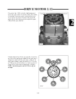
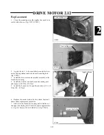
18 Place the special tool on the bearing nut and remove
the bearing nut. (fig. C2308, C2309).
Special tool
Bearing nut
Front cover
Retaining screws
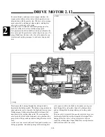
19 Remove the drive motor from the vise and remove
the screws retaining the front cover to the bearing hous-
ing. (fig. C2310, C2311). Replace the seals with new at
time of assembly.
Содержание 1300 ProTough
Страница 1: ...REPAIR MANUAL 135 137 153 1300 ProTough Publication No 49702 September 2004 THOMAS...
Страница 13: ...1 HYDRAULIC SCHEMATIC 1 1 1 3 C4475...
Страница 61: ...1 1 51 NOTES...
Страница 86: ...2 25 2 TANDEM PUMP PARTS DIAGRAM 2 11 C 2875 6 1 5 5 2 7 8 10 11 12 13 4 4 4 4 3 3 9 2 LN000500 onward shown...


