2-9
2
1 Check oil level in reservoir:
a .fill to proper level as marked on site tube.
2 Inspect external control linkage for:
a. misadjustment or disconnection
b. binding, bending or breakage
c. misadjusted, damaged or broken hydroback
3 Inspect servo control valve for: ( if used )
a. proper inlet pressure
b. misadjusted or damaged neutral return spring
c. galled or stuck control spool
d. galled or stuck servo piston
4 Inspect heat exchanger for:
a. obstructed air flow
b. improper plumbing ( inlet to outlet )
c. obstructed fluid flow
5 Inspect inlet filter or screen for:
a. plugged or clogged screen or filter
b. obstructed inlet or outlet
c. open inlet to charge pump ( open line )
6 Check charge pressure:
a. follow test procedures section 2.5
7 Inspect charge relief valve for:
a. poppet held off seat
b. damaged or broken spring
c. damaged valve seat
d. improper charge relief setting
8 Inspect charge pump for:
a. broken or missing drive coupling
b. damaged or missing o-rings
c. galled or broken geroter set
9 Inspect system relief valves for:
a. damaged or broken springs
b. valve held of seat
c. damaged valve seat
d. improper pressure relief settings
10 Check system pressure:
a. follow test procedures section 2.5
11 Inspect hydraulic motor for:
a. disconnected coupling
TROUBLE SHOOTING 2.4
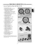
System Diagnosing Steps And Special Tools
C1699
C1704
C1698
Pressure gauges
Vacuum gauge
30 in Hg
Adapter fittings
C1697
Caps and plugs
0 - 500psi (34.5bar)
0 - 5000psi (345bar)
Photographs in the right hand column show some of the
special tools that may be required to diagnose and repair
the hydrostatic system.
Содержание 1300 ProTough
Страница 1: ...REPAIR MANUAL 135 137 153 1300 ProTough Publication No 49702 September 2004 THOMAS...
Страница 13: ...1 HYDRAULIC SCHEMATIC 1 1 1 3 C4475...
Страница 61: ...1 1 51 NOTES...
Страница 86: ...2 25 2 TANDEM PUMP PARTS DIAGRAM 2 11 C 2875 6 1 5 5 2 7 8 10 11 12 13 4 4 4 4 3 3 9 2 LN000500 onward shown...

