1
1-42
Cylinder Inspection
1
Inspect the cylinder rod for scratches, dents and other
damage. Minor rod damage may be repaired using a fine
abrasive. Major scratches or dents are not repairable and
the rod must be replaced. The chrome surface must be
intact to provide a rust resistant surface. Blemishes on the
rod will damage the rod seal and wiper and will cause
leaking after a short period of use.
2
Inspect the cylinder rod threads. The threads must be
in good condition to withstand the high torque required to
secure the piston assembly to the rod.
3
Inspect the gland nut for nicks, burrs or other
damage. Minor damage may be repaired using a fine
abrasive.
Smooth down edges that could damage seals and cause
leakage.
4
Inspect the gland nut threads for damage.
5
Inspect the piston assembly for damage. Remove
minor scratches or damage with a fine abrasive.
6
Using a suitable light, inspect the cylinder barrel bore
for scratches, dents, burrs or any other damage. Replace
the cylinder barrel if there is any evidence of damage.
7
Inspect the cylinder barrel threads for damage. The
threads must be in good condition to withstand the high
torque required to secure the gland nut assembly to the
cylinder barrel.
C3734
C3777
C3736
4
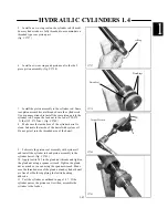
Apply system oil to the cylinder rod and assemble
the gland nut assembly to the rod. (fig. C3736)
2
Install a new wiper seal in the gland nut. (fig. C3734,
C3777)
3
Install a new gland nut o-ring seal. (fig. C3734,
C3777)
1
Install a new gland nut rod seal. Form the seal into
an oval shape and place it into the gland nut, with the “U”
side of the seal facing the barrel end, and slip the seal into
the groove. (fig. C3734,C3777)
Cylinder Assembly
HYDRAULIC CYLINDERS 1.4
O-Ring
Gland Nut
Snap In
Wiper Seal
Rod Seal
Rod Seal
Snap In
Wiper Seal
Gland O-Ring
Содержание 1300 ProTough
Страница 1: ...REPAIR MANUAL 135 137 153 1300 ProTough Publication No 49702 September 2004 THOMAS...
Страница 13: ...1 HYDRAULIC SCHEMATIC 1 1 1 3 C4475...
Страница 61: ...1 1 51 NOTES...
Страница 86: ...2 25 2 TANDEM PUMP PARTS DIAGRAM 2 11 C 2875 6 1 5 5 2 7 8 10 11 12 13 4 4 4 4 3 3 9 2 LN000500 onward shown...


