background image

2-40

2

DRIVE MOTOR 2.12

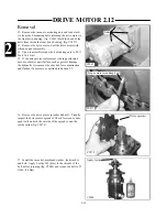
13 Separate the geroler section from the rest of the
motor. (fig. C2300, C2303) Place your fingers between
the sections as you lift the geroler section to prevent the
rollers and gear from spilling out.

C2303

C2300

C2301

C2302

Disassembly (cont’d)

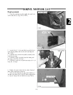
14 Inspect the gears and rollers for wear such as scratch-
es and pitting. (fig. C2301, C2302) Replace worn parts as
required. Do not mix the position of the rollers in the ger-
loer section housing.

Содержание 1300 ProTough

Страница 1: ...REPAIR MANUAL 135 137 153 1300 ProTough Publication No 49702 September 2004 THOMAS...

Страница 2: ...IABLE TO PURCHASER OR ANYONE ELSE FOR ANY INDIRECT INCIDENTAL CONSEQUENTIAL PUNITIVE ECONOMIC COMMERCIAL OR SPECIAL LOSS WHICH IS IN ANY WAY ASSOCIATED WITH A PRODUCT THIS INCLUDES ANY LOSS OF USE OR...

Страница 3: ...Thomas loader The serial number plate is located at the rear of the machine on the left hand side hydraulic oil tank In the event that the serial number plate is missing the serial number is stamped...

Страница 4: ...ION It is advisable to use a protective cream before work to prevent irritation and skin contamination After work clean your hands with soap and water Solvents such as white spirits paraffin etc may h...

Страница 5: ...ause damage to components such as seals etc and can cause skin irritation Solvents should be checked that they are suitable not only for the cleaning of components and individual parts but also that t...

Страница 6: ...ngs must be taken with the gauges specified The correct procedure should be rigidly observed to prevent damage to the system or the equipment and to eliminate the possibility of personal injury To avo...

Страница 7: ...correct tool for the job C HOSES AND TUBES Always replace hoses and tubes if the end connections are damaged Be sure any hose installed is not kinked or twisted When installing a new hose loosely conn...

Страница 8: ...nded puller to reduce the risk of bearing or related component failure These bearings and bushings are subjected in normal operation to high working loads and adverse conditions Be sure during normal...

Страница 9: ...Tests 2 5 Towing Procedure 2 6 Flushing The Hydraulic System 2 7 Start up Procedure 2 8 Gear Pump Replacement 2 9 Tandem Pump Replacement 2 10 Tandem Pump Parts Diagram 2 11 Drive Motor 2 12 Torque S...

Страница 10: ...it 5 10 Auxiliary Circuit 5 11 Accessory Circuit 5 12 Trouble Shooting 5 13 Section 6 Main Frame Quick Tach 6 1 Boom Arms 6 2 Boom Support 6 3 ROPS 6 4 Rear Door 6 5 Section 7 Engine Maintenance 7 1 C...

Страница 11: ...53 pg 1 26 31 Control Valve Disassembly Repair 1300 135 pg 1 32 35 Hydraulic Cylinders 1 4 General Information pg 1 36 Testing Piston Seals pg 1 37 Lift Cylinder Replacement pg 1 38 Tilt Cylinder Repl...

Страница 12: ...tems A3 B3 are reversed for hand control operated machines Hydraulic fluid comes out the port closest to the spool end of the valve when the spool is pushed in Hydraulic fluid received at the fixed en...

Страница 13: ...1 HYDRAULIC SCHEMATIC 1 1 1 3 C4475...

Страница 14: ...Series Type Main Relief Pressure 2400 psi 165 5 bar Zero Flow Reservoir Capacity 8 US gallons 30 3 liters Fluid Type 10W30 API SJ Oil Reservoir Filtration 100 Micron System Filtration 5 Micron Oil Co...

Страница 15: ...rom this operation is ported to the next valve section which allows operation of more than 1 function at the same time This is a series type valve function Each spool end contains a centering spring w...

Страница 16: ...ce gear pump in reverse order 6 If the hydraulic system has been contaminated by pump or other failure you must follow the cleaning procedure outlined in section 2 7 7 Start the engine and check for l...

Страница 17: ...ce of lubrication during assembly can cause the unit to seize after a few minutes of running 4 Care Of Surface Treatment Be careful when handling all the internal surfaces especially bearings gears an...

Страница 18: ...ssembly 9 Wear Plate 3 Seal Ring 10 Load Ring 4 Wear Plate 11 Preload Ring 5 Gear Plate 12 Seal Ring 6 Dowel Pin 13 Body Assembly 7 Idler Shaft 14 Shaft Seal 1 8 Disassembly 137 153 GEAR PUMP 1 2 1 3...

Страница 19: ...ting any parts or damaging the mounting pilot 2 Use a Allen head socket wrench to loosen the bolts on the cover assembly fig C4349 Next completely unscrew the bolts and remove them Inspect the threads...

Страница 20: ...eed to mark the relative positions of the gear mesh drive gear tooth and idler gear tooth and the body so they can be reassembled in the same position Carefully remove the gear plate fig C4353 Remove...

Страница 21: ...any damaged seals 9 Remove the shaft seal in the body assembly if applicable Place the flange on the work surface Using internal snap ring pliers remove the snap ring Check the seal quality and remov...

Страница 22: ...l into the body assembly if applicable Prepare the body and shaft seal by lightly lubricating with grease Seat the seal in the body assembly by hand Then using a shaft seal installation tool press the...

Страница 23: ...correct bearing bore Align the idler shaft with the assembly marks to ensure assembly is installed with the same orientation as before assembly Place the idler shaft in the correct bearing bore into t...

Страница 24: ...ls and dowel pins fig C4351 Lightly tap the back of the cover until dowel pins are completely engaged Check the seal making sure it is seated properly with no foreign material pinched between the surf...

Страница 25: ...haft Seal 2 Back Plate 10 Washer 3 Body Assembly 11 Cap Screw 4 Drive Gear 12 Back up Gasket 5 Idler Gear 13 Seal 6 Plug 14 Key for Straight Shaft Models 7 Wear Plate 15 Washer 8 O Ring Seal 16 Retain...

Страница 26: ...y and back plate to assure proper alignment when reassembling 3 Place the gear pump in a vise with the shaft side up fig C2090 4 Remove the cap screws and washers retaining the pump sections together...

Страница 27: ...ssembly in the gear pocket and tap the protruding end with a plastic hammer fig C1897 12 Remove the shaft seal and washer from the front plate using a blunt punch from the back side fig C1900 10 Remov...

Страница 28: ...e body wear plate and front plate is correct upon reassembly Note the 2 two half moon shaped cavities in the body The smaller half moon port cavity must be on the pressure side of the gear pump The si...

Страница 29: ...arge port opening in the back plate is the inlet side 9 Install the cap screws and washers fig C2089 Torque the evenly in a crisscross pattern to 25 28 ft lbs 34 38 Nm 10 Place the washer over the dri...

Страница 30: ...ll the gear pump to the loader as outlined on page 1 6 C4228 Start up Procedure 1 Mount the gear pump to the loader fig C4228 2 Connect the hydraulic lines 3 Start the pump and run for 3 minutes each...

Страница 31: ...prevent meter and gauge damage Be sure to connect a return line to the male auxiliary hydraulic quick coupler fig C4230 2 Start the engine and engage the auxiliary hydraulic system Increase the engin...

Страница 32: ...cted or the filter in the relief valve is clogged Control Valve Replacement 1 Remove any attachment and shut off the engine Turn the key on with the safety devices activated so the pedals can be moved...

Страница 33: ...in the hydraulic reservoir and top off if necessary 11 Start the engine and cycle the various hydraulic functions to check for leaks Make sure the control valve lock system is functioning properly Do...

Страница 34: ...x 20 screw 18 Tilt endcap kit 19 Tilt positioner kit 20 Load check valve 21 Backpressure valve 22 Blanking plug 23 Anti cavitation valve 24 O ring seal 25 O ring seal 26 Control body 27 Joint 28 12VD...

Страница 35: ...ft endcap 11 M5 x 65 screw 12 Tilt positioner kit 13 Tilt endcap 14 Auxiliary positioner kit 15 Auxiliary endcap kit 16 SAE 10 plug 17 Load check valve 18 SAE 12 plug 19 Lift spool 20 Tilt spool 21 Au...

Страница 36: ...ve the spring return detent kit and spring center cap locks fig C3704 C3706 2 Remove the solenoid coils and locking pin from the valve lock block fig C3699 There are 2 O ring seals located on either s...

Страница 37: ...ve to release the hardened ball from the hole in the spool end and then pull away from the valve 5 Pull out the spool fig C3713 As you pull out the spool note it s smooth action as it comes out of the...

Страница 38: ...a new detent kit Apply Loctite 542 to the threads of the detent when installing to the spool Apply Castrol Spheerol TN grease to the inside of the spring cover 8 Fit the seal washer to the control val...

Страница 39: ...assembly tighten the screws to 4 9 ft lbs 6 6 Nm 12 Install the spring return centering cover and tighten the mounting screws evenly to 4 9 ft lbs 6 6 Nm Install the end cap to the cover and tighten...

Страница 40: ...remove the spool from the spool bore It should come out smoothly without binding or snagging throughout it s travel 7 Inspect the spool and spool bore for abnormal wear fig C4245 Replace the spool and...

Страница 41: ...assembly to the spool apply Loctite 542 to the threads and tighten the screw to 17 7 ft lbs 24 Nm 9 Upon assembly use new O ring seals fig C4248 Don t over look the small O ring seal between the cylin...

Страница 42: ...bly 1 Remove the pressure relief valve Discard the O rings fig C3746 2 Remove the solenoid coils and locking pin from the valve lock block fig C3748 There are 2 O ring seals located on either side of...

Страница 43: ...s it comes out of the valve body The spool should move freely and smoothly in the bore of the valve body Check the control valve spool and bore for scuff marks or abnormal wear Replace the spool and o...

Страница 44: ...serting to the control valve 19 Place the cable end of the spool in a vice or insert a screw driver through the clevis pin holes to keep it from turning The detent is threaded to the spool and can be...

Страница 45: ...tite type 542 to the threads Tighten the detent to the spool at 17 7 ft lbs 24 Nm fig C2254 11 Install the spring return centering cover and tighten the mounting screws evenly to 4 9 ft lbs 6 6 Nm Ins...

Страница 46: ...d chrome plated The cylinder barrels are micro honed to close tolerance straightness and smooth finish for long piston packing seal life All cylinders have a 2 piece piston assembly made of ductile ir...

Страница 47: ...r fixed end of the cylinder in a vice or support to hold the cylinder 5 Extend the cylinder ram about 6 8 Fill the fixed end cylinder port with hydraulic oil using a funnel 6 Cap both ports with a 3 4...

Страница 48: ...vent brooming of the pin remove the rear pin fig C4253 Brooming the pin makes it difficult to remove 5 Remove the cylinder from the loader 6 Upon replacement inspect the pivot pins and cylinder bushin...

Страница 49: ...the bolts retaining the pivot pins to the loader and remove the bolts fig C3649 5 Remove the pivot pins by tapping out with a brass drift pin fig C4252 6 Remove the cylinder from the loader 7 Upon re...

Страница 50: ...he gland nut threads are coated with loctite bonding agent at time of assembly It may be necessary to apply heat to the gland nut and cylinder barrel threaded area with a torch to ease removal fig C37...

Страница 51: ...he gland nut assembly fig C3734 NOTE Some seal designs may vary from illustration 9 Remove the gland nut assembly from the cylinder rod fig C3733 8 Depending on the design of the rear piston non threa...

Страница 52: ...assembly for damage Remove minor scratches or damage with a fine abrasive 6 Using a suitable light inspect the cylinder barrel bore for scratches dents burrs or any other damage Replace the cylinder...

Страница 53: ...e the cylinder to the loader 7 Install the piston assembly to the cylinder rod Some rear piston assemblies are threaded onto the cylinder rod Use a spanner wrench to install the rear piston part to th...

Страница 54: ...ion Filter Replacement The hydraulic oil filter must be changed after the first 50 hours of operation and every 150 hours thereafter 1 Lower the boom arms shut off the engine and engage the parking br...

Страница 55: ...ig C1880 If necessary the whole engine may need to be moved if adjustment cannot be made by moving the radiator General Information Cooler Replacement 1 Lower the boom arms engage the parking brake an...

Страница 56: ...min filter for replenishing the hydraulic reservoir The oil fill cap is also a reservoir vent or breather and contains a 10 micron filter to remove air borne particles General Information Checking Th...

Страница 57: ...in the hydraulic reservoir by removing the inspection cover on the reservoir located in the engine compartment fig C1871 Clean the excess silicone from the cover and reservoir NOTE You may need to rem...

Страница 58: ...l reservoir and pump Load check valve not functioning Inspect and replace damaged parts 1 4 Control valve spool spring return mech anism not functioning Inspect and replace damaged parts 1 4 Control l...

Страница 59: ...7 7 11 8 1 4 1 8 Torque Chart NOTE all torques are in ft lbs Multiply by 1 36 Nm HOSE SIZE 37 JIC FITTINGS HOSE SIZE ORB FITTINGS 1 4 9 to 10 1 4 14 to 16 5 16 15 to 16 5 16 18 to 20 3 8 20 to 22 3 8...

Страница 60: ...quart U S liquid quart Imperial gallon U S gallons Imperial gallon min BY 0 092 903 4 448 222 25 4 0 304 8 1 609 344 0 453 592 28 35 608 277 4 16 0185 0 745 700 6 894 757 0 069 0 070 303 1 8 F 32 0 1...

Страница 61: ...1 1 51 NOTES...

Страница 62: ...2 11 Flushing The Hydraulic System 2 7 General Information pg 2 12 Cleaning pg 2 13 14 Start up Procedure 2 8 Procedure pg 2 15 Gear Pump Replacement 2 9 Procedure pg 2 16 Tandem Pump Replacement 2 10...

Страница 63: ...A Hydrostatic Circuit and System Pressure Schematic High Pressure Relieved at 5000 psi 345 bar Aux Press Relief Set at 2400 psi 165 5 bar System Charge Pressure 200 psi Minimum 13 8 bar Return Pressur...

Страница 64: ...f Valve Setting 5000 psi 345 bar Max Allowable Case Pressure 25 psi 1 7 bar Charge Pump Type External Gear Pump Sauer Danfoss Charge Pressure 200 psi Min 13 8 bar Hydrostatic Repair Manual Thomas P N...

Страница 65: ...elief Valve Setting 5000 psi 345 bar Max Allowable Case Pressure 25 psi 1 7 bar Charge Pump Type External Gear Pump Eaton Charge Pressure 200 psi Min 13 8 bar Hydrostatic Repair Manual Thomas P N 4423...

Страница 66: ...mped and the speed of the loader is increased The drive motor which is a fixed displacement type delivers a constant output torque for a given pressure throughout the speed range of the motor The move...

Страница 67: ...m Operating Hot Check oil level in reservoir Inspect heat exchanger Check charge pressure Low Inspect inlet screen or filter Repair or replace Repair or replace Repair or replace Reduce system load Re...

Страница 68: ...charge pressure Inspect motor Inspect charge relief valve Inspect inlet screen or filter Replace pump and motor Inspect charge pump Repair or replace Repair or replace Repair or replace Replace Repair...

Страница 69: ...m load Repair or replace Repair or replace Defective Defective Clogged Defective High Low Defective OK OK OK OK OK OK Inspect inlet screen or filter Inspect motor Check sys tem pressure Replace pump a...

Страница 70: ...a follow test procedures section 2 5 7 Inspect charge relief valve for a poppet held off seat b damaged or broken spring c damaged valve seat d improper charge relief setting 8 Inspect charge pump for...

Страница 71: ...8 14 O Ring fitting 500 psi Gauge 34 5 bar 1 1 16 12 O Ring Fitting C4257 C4258 WARNING Use caution when dealing with hydraulic fluid under pressure Escaping fluid under pressure can pene trate the s...

Страница 72: ...override for the brake valve has been incorporated for use by Thomas Dealers The normal position of the plunger is down and turned into the locked position To release the brake turn the release plunge...

Страница 73: ...roscopic contaminates include the following 1 Cylinder rod seal leaks 2 Control valve spools do not return to neutral 3 Hydraulic system has a high operating temperature 4 Components wear rapidly Visi...

Страница 74: ...apa ble of sustaining minimum of 2000 psi 138 bar and has a back pressure gauge to the auxiliary couplings fig C1687 C1688 3 Start the engine and let it idle at approximately half throttle 4 Engage th...

Страница 75: ...oil flows clear 9 Connect 1 hose each on each cylinder to the fixed end of the cylinder barrel 10 Move the foot pedal or control lever to extend the cylinder rods This will flush the oil from inside...

Страница 76: ...r Repeat this step turning the engine over in 15 second interval 5 or 6 times This will fill the rest of the hydraulic hoses 7 Reconnect the engine stop solenoid or replace the fuse 8 Start the engine...

Страница 77: ...r pump 5 Replace gear pump in reverse order 6 If the hydraulic system has been contaminated by pump or other failure you must follow the cleaning proce dure outlined in section 2 7 7 Start the engine...

Страница 78: ...C2068 7 Remove the 2 nuts on the u joint access panel fig C4260 to gain access to the rear mounting bolts for the tandem pump Tip the top of the panel rearward and pull the panel forward to remove 8...

Страница 79: ...onnect A Hose no 1 connects to the bottom port of the left hand drive motor B Hose no 2 connects to the top port of the left hand drive motor C Hose no 3 connects to the top port of the right hand dri...

Страница 80: ...p fig C4259a Torque the fittings and hoses to the specifications listed in the Torque Chart Section 2 13 C4259a C2072 Charge line IMPORTANT When making repairs to the hydraulic system keep the work ar...

Страница 81: ...rvoir Never use your hands to check for hydraulic leaks 19 Make adjustments to the steering controls steering locks and restraint bar cables as required Follow the pro cedures for control adjustments...

Страница 82: ...GRAM 2 11 C1881 Sauer Danfoss Series 40 M35 Rear Pump 39 40 45 44 43 42 41 46 47 48 49 1 2 3 1 4 5 4 6 11 11 12 7 8 9 9 10 10 13 14 15 15 15 16 17 18 19 19 20 51 51 38 50 37 36 35 34 33 32 31 20 21 21...

Страница 83: ...lief poppet 27 Pump housing 28 End cap 29 Plug 30 O ring seal 31 O ring seal 32 Coupler 33 O ring seal 34 Screw 35 Swashplate 36 Thrust plate 37 Piston assembly 38 Slipper retainer 39 Slipper retainer...

Страница 84: ...MP PARTS DIAGRAM 2 11 C2007 Sauer Danfoss Series 40 M35 Front Pump 39 40 44 43 42 41 1 2 3 5 11 11 12 7 8 9 9 10 10 13 14 15 15 15 16 17 17 18 19 19 20 38 37 36 35 34 33 32 31 20 21 21 22 23 24 25 25...

Страница 85: ...Bracket 25 Relief valve kit 26 Cylinder block kit 27 Pump housing 28 End cap 29 Swashplate 30 Thrust plate 31 Piston assembly 32 Slipper retainer 33 Slipper retainer guide 34 Special washer 35 Slipper...

Страница 86: ...2 25 2 TANDEM PUMP PARTS DIAGRAM 2 11 C 2875 6 1 5 5 2 7 8 10 11 12 13 4 4 4 4 3 3 9 2 LN000500 onward shown...

Страница 87: ...000101 onward Eaton Brand 1 Gear Pump LN000500 onward Eaton Brand 2 O ring 3 Seal Swashplate housing 4 O ring Swashplate cover 5 Relief Valve 345 Bar Setting LE009073 onward LN000101 onward 6 O ring C...

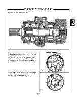
Страница 88: ...ring fig C153 of the geroler assembly is similar to an internal gear that is held in a fixed position by securing it to the motor housing The rotating inner gear called a star orbits inside the secure...

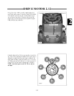
Страница 89: ...f these fluid pockets are subject to fluid pressure causing star rotation and the opposing half are connected to the return line When pressure is introduced into the fluid pockets on the right side of...

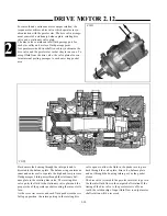
Страница 90: ...speed without further gear reduction C2299 C166 Example shown in fig C166 is one complete star orbit or one sixth of the output shaft rotation The star must travel through 6 complete orbits for each...

Страница 91: ...balance plate The balance ring contains an inner and outer seal to separate the high and low pressure fluid passages Fluid passes through the stationary bal ance plate to the rotating disc valve The r...

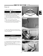
Страница 92: ...lug Upper fill check C2073 Inspection cover C2082 Brake hose C2074 Hi pressure hoses 9 Disconnect the brake line hose and the case drain hose from the drive motor Cap the hoses and adapter fit tings i...

Страница 93: ...is being performed because of major parts failure such as geroler damage the hydraulic system must be checked for contamination and flushed if necessary as outlined in Section 2 7 C2081 Nuts C2080 C2...

Страница 94: ...approximate ly 1 9 gal 7 litres of 10w30 API SJ oil fig C1888 Replacement 1 Clean the mounting areas thoroughly that need to be sealed with silicone fig C2078 C2076 2 Apply a bead 1 4 of an inch thick...

Страница 95: ...ing for proper torque 15 Install the wheels and torque the nuts at 100 to 110 ft lbs 136 to 149 Nm 16 Install shields and seat let loader down to ground and test drive to check performance DRIVE MOTOR...

Страница 96: ...ng washer 5 Spacer 6 O ring seal 7 O ring seal 8 Valve drive shaft 9 Channel plate 10 Disc valve 11 Balance plate 12 Guide pin 13 O ring seal 14 Guide pin 15 Gearwheel set 16 Intermediate plate 17 O r...

Страница 97: ...21 Front cover 22 Dust seal ring 23 Screws Danfoss OMT FL Brake Diagram C1893 Index Fig C1893 shows an exploded view of the hydraulic torque motor brake Before disassembling the torque motor and or b...

Страница 98: ...t in reassembly fig C2287 5 Remove the 4 bolts from the drive motor valve hous ing fig C2290 Upon reassembly torque the bolts in a criss cross pattern at 130 135 ft lbs 177 183 5 Nm DRIVE MOTOR 2 12 C...

Страница 99: ...1 2293 DRIVE MOTOR 2 12 C2291 C2292 C2294 C2293 Shuttle valve plug Disassembly cont d Remove shuttle valve plugs Shuttle valve springs Shuttle valve poppet 8 Push out the shuttle valve poppet using th...

Страница 100: ...e Disassembly cont d Spacer Valve housing Balance plate Spring washers Notch Locating pin Channel plate Disc valve Channel plate Disc valve 11 Remove the disc valve and balance plate from the valve ho...

Страница 101: ...he sections as you lift the geroler section to prevent the rollers and gear from spilling out C2303 C2300 C2301 C2302 Disassembly cont d 14 Inspect the gears and rollers for wear such as scratch es an...

Страница 102: ...bly Disassembly cont d Cardan shaft drive Intermediate spacer Special tool Bearing nut 2 4 in 60 mm 3 in 76mm 6mm machine screws 17 A special tool will be required as shown in fig C2306 to remove the...

Страница 103: ...on the bearing nut and remove the bearing nut fig C2308 C2309 Special tool Bearing nut Front cover Retaining screws 19 Remove the drive motor from the vise and remove the screws retaining the front c...

Страница 104: ...ont d Output shaft and large bearing Small bearing Bearing housing bolts Separate section 23 Separate the bearing housing sections fig C2315 A mallet may be required to assist removal 22 Remove the bo...

Страница 105: ...e piston fig C2317 There are inner and outer springs 26 Remove the piston from the housing by pushing through from the output shaft side fig C2318 27 Remove the brake disc assemblies Note the position...

Страница 106: ...til the last plate to be installed is a fibre plate 3 Install the brake disc spacer ring to the housing fig C2320 2 Install the front cover to the housing and torque the screws to 8 9 ft lbs 12 Nm fig...

Страница 107: ...Add steel plate second Brake discs Piston Springs Bearing housing Align spring to hydraulic port 6 Install the piston to the housing over the brake discs fig C2318 Use new seals when assembling the mo...

Страница 108: ...put shaft fig C2313 in the following sequence a Apply pressure 175 psi 12 bar to the brake ports to release the brakes b Press the bearing onto the output shaft with a force of 780 pounds of force 350...

Страница 109: ...used to locate the plate to the notch in the housing Cardan shaft 12 Install the cardan drive shaft to the output shaft fig C2328 13 Note the holes in the intermediate spacer and the geroler section...

Страница 110: ...the bottom of a tooth in the external rotor teeth fig C2331 17 Install the valve drive lining up the marks on the valve drive to the gearwheel set fig C2333 16 Mark the bottom of a spline tooth on th...

Страница 111: ...le Hole Timing mark Timing mark Disc valve hole Turn counter clockwise 21 Install new seals to the balance plate install the springs and install the balance plate to valve housing fig C2297 Note the l...

Страница 112: ...2 12 22 Apply petroleum jelly to the spacer fig C2337 Install the spacer to the valve housing fig C2338 23 Install the valve housing to the drive motor fig C2339 24 Install the shuttle valve piston f...

Страница 113: ...C2293 26 Install the shuttle valve plugs fig C2292 Be sure to use new seals when assembling the motor 28 Install the restrictor and replace the plug fig C2289 27 Install the bolts to the drive motor a...

Страница 114: ...ng torque specifications are for steel ORB fittings into aluminum HOSE SIZE ORB FITTINGS HOSE SIZE ORB FITTINGS 1 4 5 to 7 3 4 40 to 45 5 16 8 to 10 7 8 50 to 55 3 8 10 to 12 1 90 to 99 1 2 21 to 24 1...

Страница 115: ...l pg 3 3 Drive Chain 3 3 Checking pg 3 4 Adjusting pg 3 5 Removal pg 3 6 Installation pg 3 7 Chain Tightener 3 4 Removal pg 3 8 Inspection pg 3 8 Installation pg 3 9 Drive Motor Sprocket 3 5 Replaceme...

Страница 116: ...ecifications Chain Tightener Clamp Nuts 150 lbs ft 203 nm Motor Sprocket Bolt 25 lbs ft 34 nm Wheel Nuts 100 110 lbs ft 135 149 nm Tire Pressure 50 psi 345 Kpa Specifications Maintenance Initial Check...

Страница 117: ...capacity per side is 7 liters 1 9 gal 6 Replace all plugs WARNING IMPORTANT Check the final drives closely for damaged seals or other leaks if the oil level is excessively low Never work under a raise...

Страница 118: ...997 Slide the special tool into the filler hole and use the hooked end to grab under the chain fig C372 Pull upward on the tool using a force equal to approxi mately 30 lbs 13 6 kg pull The special to...

Страница 119: ...ce the inspection covers If proper chain tension adjustment can not be reached using the adjuster plate the chain will need to be replaced Do not remove extra links from the chain It has reached it s...

Страница 120: ...arting the engine and engaging the steering control Be sure the loader is securely raised clear of the ground 7 Loosen the 3 chain tightener nuts Refer to Adjusting the drive Chain page 3 5 8 Loosen t...

Страница 121: ...3 5 9 Replace the inspection cover using silicone Do not over tighten the inspection cover nuts 18 lbs ft maxi mum 24 5 nm 10 Replace the wheels and torque the wheel nuts to 100 to 110 lbs ft 136 to 1...

Страница 122: ...embly as you release the nuts The tightener is now free to be removed C1173 Adjuster plate Support plate Tightener bracket L H R H Tightener bolt assembly Sprocket Thrust washer Cage roller bearing Id...

Страница 123: ...e chain tightener The support plate holes are drilled off center Install the sup port plate so that it extends beyond the chain tightener bracket on the bolt head side fig C235 C234 C235 Apply elastom...

Страница 124: ...located between the axle assemblies fig C2073 4 Loosen the drive chain to its slackest position fig C2009 See page 1 6 for assistance C2073 Loosen chain Remove inspection cover C2009 Drive sprocket bo...

Страница 125: ...AXLE ASSEMBLY 3 6 C1172 12 11 10 9 8 7 6 5 5 4 4 3 2 2 1 Axle Assembly T 135 S 1 Axle 7 Wheel Stud 2 Key 8 Wheel Nut 3 Seal 9 Axle Sprocket 4 Bearing 10 Washer 5 Race 11 Castle Nut 6 Axle Tower 12 Cot...

Страница 126: ...page 3 6 8 FRONT AXLE Remove the foot peal assembly if so equipped Refer to Section 4 9 Remove the inner axle cover plate from the final drive housing fig C219 10 REAR AXLE Remove the inner axle cove...

Страница 127: ...g or nicks Minor scratches may be removed using fine emery cloth Replace the axle if worn excessively 2 Inspect the axle threads for damage Replace axle if the threads are non serviceable 3 Inspect th...

Страница 128: ...le oil seal with light grease 6 Install the seal onto the axle The seal part number stamping must face the flange side of the axle fig C222 7 Using a press install the front or outer bearing onto the...

Страница 129: ...t sealant to the outer edge of the axle oil seal fig C212 Take care make sure none gets on the bearing surface C220 C225 C212 C226 13 Start the axle into the drive sprocket Place the axle washer and c...

Страница 130: ...nd remove the axle oil seal installation tools AXLE ASSEMBLY 3 6 C206 C217 C216 19 Install the axle washer and castle nut Tighten the castle nut to remove all axle bearing end play Zero pre load Conti...

Страница 131: ...ion to allow stud removal without removing the axle assembly 2 Strike the stud with a hammer to remove from the axle flange fig C209 Axle Stud Replacement C209 C210 C211 4 Place a wheel nut on the stu...

Страница 132: ...the chain tension every 150 hours 3 3 Drive motor sprocket failure Inspect the drive sprocket and splines Replace parts as required 3 5 2 Refer to the hydrostatic drive section Diagnose and make repai...

Отзывы: