1
GEAR PUMP 1.2
Disassembly
1.
General
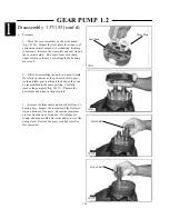
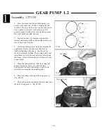
The following is a detailed procedure for disassembly
and assembly of the D series hydraulic gear pump. Prior
to proceeding it may be necessary to prepare some sub-
assemblies separately. The details for preparing each
subassembly are given in the following section, as well as
some general recommendations.
2.
Cleanliness
Cleanliness is the primary factor for reliable pump
performance. Wash the outside of the pump thoroughly
before disassembly and all pieces prior to assembly.
Cleaning parts with clean shop solvent and air drying is
usually adequate.
3.
Lubrication Of Moving Parts
During assembly, it is imperative to provide
lubrication with clean hydraulic oil to all the running
parts of the pump. It is also necessary to coat the seals
with grease. The absence of lubrication during assembly
can cause the unit to seize after a few minutes of running.
4.
Care Of Surface Treatment
Be careful when handling all the internal surfaces,
especially bearings, gears, and body faces. Do not touch
or score them with metal tools or cutting edges.
5.
Marking The Parts
Mark the parts before completely disassembling a
pump. The marks allow components to be reassembled in
the same relative position. This action should be applied
to the body, bearings, and gears. Scribing, bluing, or
using a felt pen to mark the outside of the body on the
inlet side is suggested to indicate the relative position of
the front flange and the rear cover to the body. Mark the
bearing blocks also on the inlet side and the gears
position relative to each other. DO NOT scribe internal
surfaces.
Mark all pieces during disassembly so that the unit
can be reassembled correctly. Installing components
incorrectly could severely damage the unit and/or
cause it to not function properly.
IMPORTANT
1-7
Содержание 1300 ProTough
Страница 1: ...REPAIR MANUAL 135 137 153 1300 ProTough Publication No 49702 September 2004 THOMAS...
Страница 13: ...1 HYDRAULIC SCHEMATIC 1 1 1 3 C4475...
Страница 61: ...1 1 51 NOTES...
Страница 86: ...2 25 2 TANDEM PUMP PARTS DIAGRAM 2 11 C 2875 6 1 5 5 2 7 8 10 11 12 13 4 4 4 4 3 3 9 2 LN000500 onward shown...


