MAINTENANCE
550E MM149 (6--96)
3-16
SCRUB HEAD
SCRUB HEAD
The scrub head houses the two scrub brushes
and the brush drive mechanisms. The scrub head
has two adjustments; scrub head height, and
scrub brush pattern.
The scrub head height adjustment sets the
minimum scrub head height. The height
adjustment should not be changed unless, due to
a major parts replacement or collision, the head
adjustment may have been altered. If the head
height is too low, excessive brush wear, engine
overheating, brush bounce, or excessive brush
drive plug and bearing wear may occur.
The scrub brush pattern adjustment determines
the amount of contact the brush has with the floor.
The brush pattern should be checked daily.
TO ADJUST SCRUB HEAD HEIGHT
1. The head height adjustment must be made
with a full solution tank and tires correctly
inflated: 85 psi (585 kPa) front for machines
below serial number 004506; 65 psi
(450 kPa) front for machines serial number
004507 and above; and 35 psi (240 kPa) for
rear tires on all machines.
NOTE: Using a different sized tire on the machine,
other than standard, will affect the head height
adjustment.
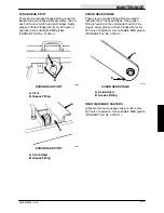
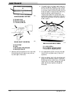
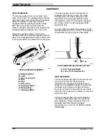
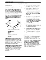
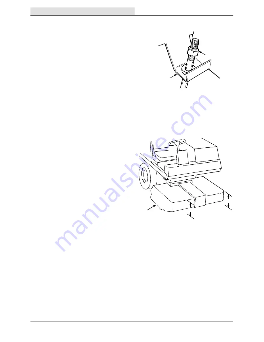
2. The head height adjusting nut is located
under the operator’s seat. The nut is
accessible by lifting up the seat. Hold the
seat up by attaching its chain to the steering
wheel.
B
A
03734
ADJUSTMENT NUT
A. Nut
B. Scrub Head Link
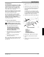
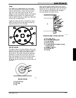
3. Adjust the nut so that the top front of the
head is 13.62 in to 13.75 in (345 to 350 mm)
from the floor.
A
B
B
01822
SCRUB HEAD ADJUSTMENT
A. Scrub Head
B. 13.62 to 13.75 in (345 to 350 mm)
4. If the scrub head is lower than 13.62 in
(345 mm), washers should be added below
the adjusting nut.
Содержание 550
Страница 10: ...GENERAL INFORMATION 550E MM149 3 94 viii ...
Страница 12: ...OPERATION 550E MM149 3 91 2 2 ...
Страница 30: ...OPERATION 550E MM149 9 00 2 20 ...
Страница 32: ...MAINTENANCE 550E MM149 3 91 3 2 ...
Страница 62: ...MAINTENANCE 550E MM149 2 05 3 32 ...
Страница 66: ...APPENDIX 550E MM149 3 91 4 4 ...
Страница 74: ...STANDARD PARTS 550E MM149 5 01 6 4 Fig 2 Replacement Brushes 1 ...
Страница 96: ...STANDARD PARTS 550E MM149 5 01 6 26 Fig 17 Electric Motor Group 1 2 3 4 5 6 ...
Страница 105: ...STANDARD PARTS 6 35 550E MM149 5 01 Fig 23 Electrical Schematic 1 2 3 4 5 01228 550E ...
Страница 106: ...STANDARD PARTS 550E MM149 5 01 6 36 Fig 23 Electrical Schematic 1 2 3 4 5 01228 550E ...
Страница 108: ...STANDARD PARTS 550E MM149 5 01 6 38 Fig 24 Power Wheel Group 2 3 4 5 6 1 5 Hydraulic Brake Assembly ...
Страница 110: ...STANDARD PARTS 550E MM149 5 01 6 40 Fig 25 Electrical Wire Harness Group 1 2 3 4 5 6 7 8 9 10 11 12 13 ...
Страница 117: ...STANDARD PARTS 6 47 550E MM149 5 01 Fig 31 Hydraulic Schematic 001330 005607 02361 550E ...
Страница 118: ...STANDARD PARTS 550E MM149 5 01 6 48 Fig 32 Hydraulic Schematic 005608 11118 550E ...
Страница 168: ...OPTIONS 550E MM149 9 99 8 18 ...
Страница 182: ...BREAKDOWNS 550E MM149 10 10 9 14 ...
Страница 196: ...CROSS REFERENCE 550E MM149 10 10 10 14 ...


