MAINTENANCE
3-25
550E MM149 (6--96)
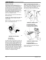
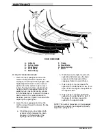
TO REPLACE REAR SQUEEGEE BLADES
1. Stop the motor and set the parking brake.
FOR SAFETY: Before Leaving Or
Servicing Machine; Stop On Level
Surface, Set Parking Brake, Turn Off
Machine And Remove Key.
2. Open the band clamp and remove all parts.
3. Place the new squeegee blade over the pins
on the frame.
4. Next, fit the two back-up strips on the pins,
inner strip down, outer strip up.
5. Position the retaining band in place and
engage the clamp.
6. The front blade is replaced in the same
manner, except that backup strips are not
used.
7. Adjust the squeegee clamp so that there is
adequate pressure to hold the squeegees in
place. The squeegee blades should be held
so they cannot be pulled from between the
locating pins. After proper adjustment is
made, lock each adjusting screw with a jam
nut.
A
C
B
A
C
B
00290
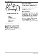
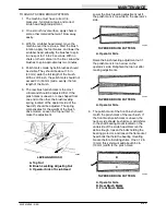
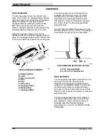
REAR SQUEEGEE
A. Band
B. Blade and Back-Up Strips on Pins
C. Clamp
B
F
A
C
B
D
E
00151
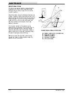
REAR SQUEEGEE CROSS-SECTION
A. Squeegee Frame
B. Band
C. Outer Back-Up Strip
D. Inner Back-Up Strip
E. Rear Blade
F. Front Blade
NOTE: Install back-up strips with outer strip up,
inner strip down.
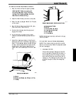
TO FACTORY ADJUST REAR SQUEEGEE
NOTE: The solution tank must be full, and the
tires must be correctly inflated to properly adjust
the rear squeegee.
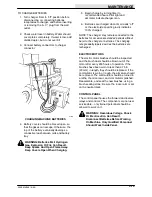
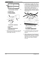
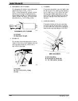
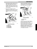
1. LINKAGE PIVOTS
Check the squeegee linkage pivot points
and, if necessary, tighten the locknuts on
each bearing joint in the linkage. Tighten
each locknut until the joint is just short of
locking up. The linkage must be snug, but
still free enough to rotate the linkage by
hand.
Содержание 550
Страница 10: ...GENERAL INFORMATION 550E MM149 3 94 viii ...
Страница 12: ...OPERATION 550E MM149 3 91 2 2 ...
Страница 30: ...OPERATION 550E MM149 9 00 2 20 ...
Страница 32: ...MAINTENANCE 550E MM149 3 91 3 2 ...
Страница 62: ...MAINTENANCE 550E MM149 2 05 3 32 ...
Страница 66: ...APPENDIX 550E MM149 3 91 4 4 ...
Страница 74: ...STANDARD PARTS 550E MM149 5 01 6 4 Fig 2 Replacement Brushes 1 ...
Страница 96: ...STANDARD PARTS 550E MM149 5 01 6 26 Fig 17 Electric Motor Group 1 2 3 4 5 6 ...
Страница 105: ...STANDARD PARTS 6 35 550E MM149 5 01 Fig 23 Electrical Schematic 1 2 3 4 5 01228 550E ...
Страница 106: ...STANDARD PARTS 550E MM149 5 01 6 36 Fig 23 Electrical Schematic 1 2 3 4 5 01228 550E ...
Страница 108: ...STANDARD PARTS 550E MM149 5 01 6 38 Fig 24 Power Wheel Group 2 3 4 5 6 1 5 Hydraulic Brake Assembly ...
Страница 110: ...STANDARD PARTS 550E MM149 5 01 6 40 Fig 25 Electrical Wire Harness Group 1 2 3 4 5 6 7 8 9 10 11 12 13 ...
Страница 117: ...STANDARD PARTS 6 47 550E MM149 5 01 Fig 31 Hydraulic Schematic 001330 005607 02361 550E ...
Страница 118: ...STANDARD PARTS 550E MM149 5 01 6 48 Fig 32 Hydraulic Schematic 005608 11118 550E ...
Страница 168: ...OPTIONS 550E MM149 9 99 8 18 ...
Страница 182: ...BREAKDOWNS 550E MM149 10 10 9 14 ...
Страница 196: ...CROSS REFERENCE 550E MM149 10 10 10 14 ...


