OPERATION
550E MM149 (3--91)
2-6
BRAKE PEDAL
The foot brake pedal operates the hydraulic disc
brakes on the two front wheels.
To stop the machine, return the directional pedal
to neutral; then apply pressure to the brake pedal.
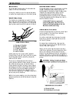
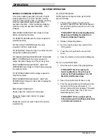
DIRECTIONAL PEDAL
The machine is propelled by two electric motors
which drive the two front wheels. Traveling speed
of the machine is varied by means of a foot pedal
which is also used to select the direction of travel.
A
B
C
E
D
00116
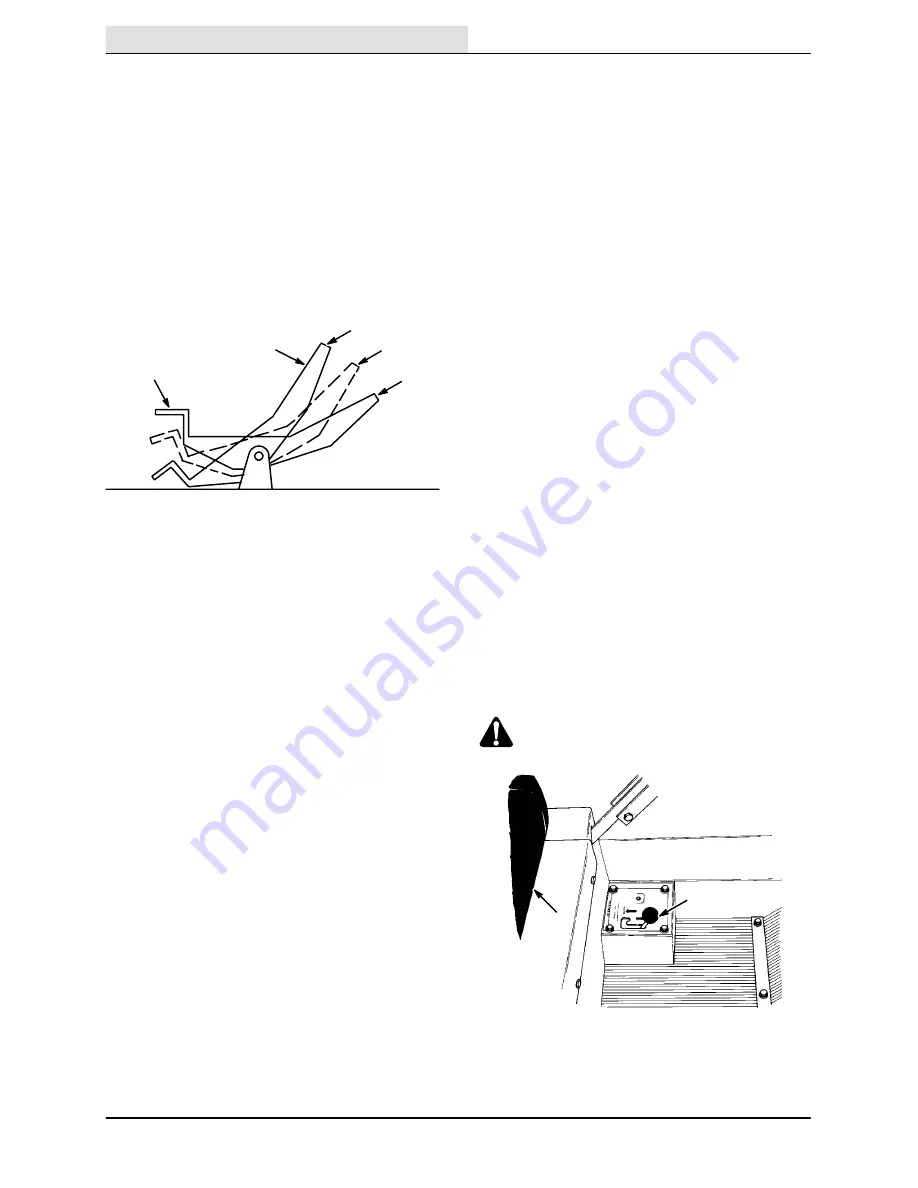
DIRECTIONAL PEDAL
A. “Reverse” Position
B. “Neutral” Position
C. “Forward” Position
D. “Toe” Portion
E. “Heel” Portion
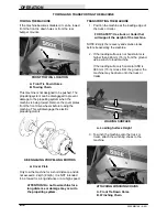
Gently press the “toe” portion of the pedal for
forward travel. Press the “heel” portion for reverse
travel. Regulate machine speed by varying the
pressure on the pedal.
There are six forward speeds; three level or
normal speeds and three climb speeds. There are
also three reverse speeds. As the directional
control pedal is pressed, the faster speed ranges
will engage--much like an automatic transmission.
There will be a three-second delay between the
time the speed switches are engaged and the
time the motor speeds up. This delay is present to
insure a smooth acceleration.
NOTE: For normal stopping, return the directional
pedal to neutral and use the foot brake to stop the
machine.
PARKING BRAKE LEVERS
The parking brake levers control brakes on all four
wheels. Pulling the brake handles up sets the
parking brakes. Pushing the brake handles down
releases the parking brakes. Always set the
parking brakes before leaving the machine
unattended and before working on the machine.
The parking brakes must be released in order to
start the machine motors.
FOR SAFETY: Before Leaving Or
Servicing Machine; Stop On Level
Surface, Set Parking Brake, Turn Off
Machine And Remove Key.
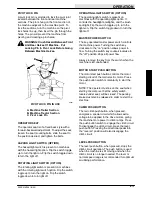
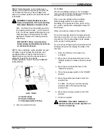
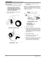
SCRUB HEAD LOCK LEVER
The scrub head lock lever controls the scrub head
lock mechanism. This locks the scrub head,
preventing it from lowering.
To set the scrub head lock, fully raise the scrub
head. Then push the scrub head lock lever into
the “LOCK” position.
To release the scrub head lock, fully raise the
scrub head. Then pull the scrub head lock lever
into the “UNLOCK” position.
Always set the scrub head lock before working
under the scrub head. The scrub head lock must
also be set whenever the machine will not be
used for an extended period of time, overnight for
example. Flat spots on the brushes will appear if
the scrub head is left down for an extended period
of time.
WARNING: Falling Scrub Head. Block
Scrub Head Up Before Working Under It.
B
A
01816
SCRUB HEAD LOCK LEVER
A. Operator Seat
B. Scrub Head Lock Lever
Содержание 550
Страница 10: ...GENERAL INFORMATION 550E MM149 3 94 viii ...
Страница 12: ...OPERATION 550E MM149 3 91 2 2 ...
Страница 30: ...OPERATION 550E MM149 9 00 2 20 ...
Страница 32: ...MAINTENANCE 550E MM149 3 91 3 2 ...
Страница 62: ...MAINTENANCE 550E MM149 2 05 3 32 ...
Страница 66: ...APPENDIX 550E MM149 3 91 4 4 ...
Страница 74: ...STANDARD PARTS 550E MM149 5 01 6 4 Fig 2 Replacement Brushes 1 ...
Страница 96: ...STANDARD PARTS 550E MM149 5 01 6 26 Fig 17 Electric Motor Group 1 2 3 4 5 6 ...
Страница 105: ...STANDARD PARTS 6 35 550E MM149 5 01 Fig 23 Electrical Schematic 1 2 3 4 5 01228 550E ...
Страница 106: ...STANDARD PARTS 550E MM149 5 01 6 36 Fig 23 Electrical Schematic 1 2 3 4 5 01228 550E ...
Страница 108: ...STANDARD PARTS 550E MM149 5 01 6 38 Fig 24 Power Wheel Group 2 3 4 5 6 1 5 Hydraulic Brake Assembly ...
Страница 110: ...STANDARD PARTS 550E MM149 5 01 6 40 Fig 25 Electrical Wire Harness Group 1 2 3 4 5 6 7 8 9 10 11 12 13 ...
Страница 117: ...STANDARD PARTS 6 47 550E MM149 5 01 Fig 31 Hydraulic Schematic 001330 005607 02361 550E ...
Страница 118: ...STANDARD PARTS 550E MM149 5 01 6 48 Fig 32 Hydraulic Schematic 005608 11118 550E ...
Страница 168: ...OPTIONS 550E MM149 9 99 8 18 ...
Страница 182: ...BREAKDOWNS 550E MM149 10 10 9 14 ...
Страница 196: ...CROSS REFERENCE 550E MM149 10 10 10 14 ...

