MAINTENANCE
550E MM149 (6--96)
3-14
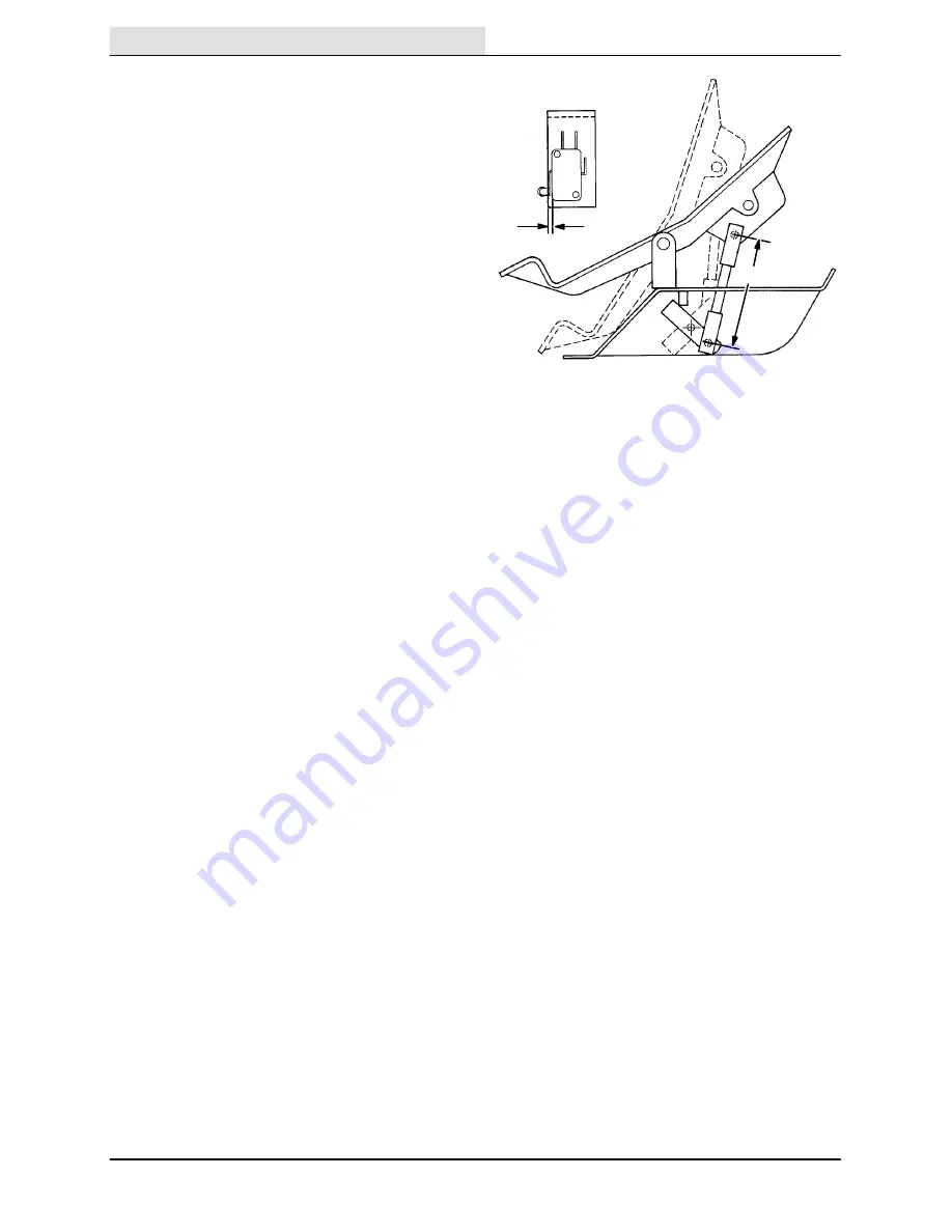
DIRECTIONAL PEDAL
The directional pedal should be readjusted after
replacing one of the control components and
whenever the machine creeps when it is in the
“neutral” position.
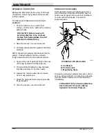
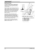
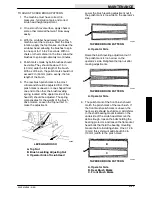
Adjust the pedal, using the following illustration as
a guide. “Neutral” position should be set first. The
pedal overtravel in “forward” and “reverse” should
be about equal. The micro switches should have
0.005 to 0.015 in (0.13 to 0.38 mm) travel left
after the switches are energized. Use feeler
gauge to measure.
The “neutral” position of the pedal is set by
adjusting the stud between the two ball joints on
the control linkage and the centering springs
under the floor pan. After the pedal is centered,
apply Loctite 290 to the spring mounting bracket
to keep the spring position stationary.
NOTE: On a smooth level floor, the machine
should not “creep” in either direction when the
pedal is at rest (in neutral).
A
B
C
D
E
01150
DIRECTIONAL PEDAL POSITIONS
A. 0.005 to 0.015 in (0.13 to 0.38 mm)
B. “Reverse” Position
C. “Neutral” Position
D. “Forward” Position
E. 4.75 in (120 mm)
Содержание 550
Страница 10: ...GENERAL INFORMATION 550E MM149 3 94 viii ...
Страница 12: ...OPERATION 550E MM149 3 91 2 2 ...
Страница 30: ...OPERATION 550E MM149 9 00 2 20 ...
Страница 32: ...MAINTENANCE 550E MM149 3 91 3 2 ...
Страница 62: ...MAINTENANCE 550E MM149 2 05 3 32 ...
Страница 66: ...APPENDIX 550E MM149 3 91 4 4 ...
Страница 74: ...STANDARD PARTS 550E MM149 5 01 6 4 Fig 2 Replacement Brushes 1 ...
Страница 96: ...STANDARD PARTS 550E MM149 5 01 6 26 Fig 17 Electric Motor Group 1 2 3 4 5 6 ...
Страница 105: ...STANDARD PARTS 6 35 550E MM149 5 01 Fig 23 Electrical Schematic 1 2 3 4 5 01228 550E ...
Страница 106: ...STANDARD PARTS 550E MM149 5 01 6 36 Fig 23 Electrical Schematic 1 2 3 4 5 01228 550E ...
Страница 108: ...STANDARD PARTS 550E MM149 5 01 6 38 Fig 24 Power Wheel Group 2 3 4 5 6 1 5 Hydraulic Brake Assembly ...
Страница 110: ...STANDARD PARTS 550E MM149 5 01 6 40 Fig 25 Electrical Wire Harness Group 1 2 3 4 5 6 7 8 9 10 11 12 13 ...
Страница 117: ...STANDARD PARTS 6 47 550E MM149 5 01 Fig 31 Hydraulic Schematic 001330 005607 02361 550E ...
Страница 118: ...STANDARD PARTS 550E MM149 5 01 6 48 Fig 32 Hydraulic Schematic 005608 11118 550E ...
Страница 168: ...OPTIONS 550E MM149 9 99 8 18 ...
Страница 182: ...BREAKDOWNS 550E MM149 10 10 9 14 ...
Страница 196: ...CROSS REFERENCE 550E MM149 10 10 10 14 ...


