MAINTENANCE
3-21
550E MM149 (12--05)
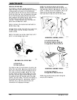
SRS WATER SPRAY DEFLECTOR
The SRS solution tank has two spray deflectors; a
lower spray deflector located on the rear
squeegee discharge tube inside the tank, and a
top spray deflector located in the top rear of the
tank. The spray deflectors deflect the spray of
water and small debris away from the walls of the
solution tank. The deflectors should be checked
for wear after every 200 hours of operations.
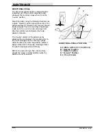
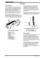
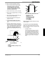
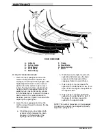
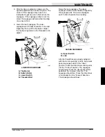
To check the lower spray deflector for wear, the
rear squeegee discharge tube must be removed
from the rear of the tank. Be sure to save the
rubber seal washers which are located on the
inside the tank. Inspect the spray deflector for
wear. If replacement is necessary, install a new
deflector into the spray deflector frames, and
mount the deflector to the rear squeegee
discharge tube. Reinstall the discharge tube into
the rear of the tank. Use a new discharge tube
gasket if the existing one is damaged.
A
C
B
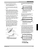
00339
CORRECT POSITIONING OF
LOWER SPRAY DEFLECTOR
A. Spray Deflector Frames
B. Spray Deflector
C. Rear Squeegee Discharge Tube
A
C
E
B D
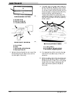
00353
INSTALLING LOWER SPRAY DEFLECTOR
A. Top Rear Clean-Out Doors
B. Bottom Clean-Out Door
C. Spray Deflector
D. Rear Bumper
E. Bottom Clean-Out Door
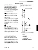
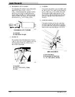
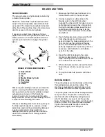
To check the top spray deflector for wear, remove
the top access cover at the top rear of the solution
tank. Inspect the deflector for wear. Remove the
deflector if replacement is necessary. Replace the
top access cover gasket if the gasket is damaged.
To install the spray deflector back into the tank,
slide the bottom of the deflector down the back of
the tank. Then, with the top cover gasket in place
on the solution tank, position the deflector to
follow the curvature of the bottom of the access
cover. Clamp the top access cover in place.
A
C
B
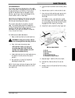
00346
INSTALLING TOP SPRAY DEFLECTOR
A. Solution Tank
B. Top Access Cover
C. Spray Deflector
Содержание 550
Страница 10: ...GENERAL INFORMATION 550E MM149 3 94 viii ...
Страница 12: ...OPERATION 550E MM149 3 91 2 2 ...
Страница 30: ...OPERATION 550E MM149 9 00 2 20 ...
Страница 32: ...MAINTENANCE 550E MM149 3 91 3 2 ...
Страница 62: ...MAINTENANCE 550E MM149 2 05 3 32 ...
Страница 66: ...APPENDIX 550E MM149 3 91 4 4 ...
Страница 74: ...STANDARD PARTS 550E MM149 5 01 6 4 Fig 2 Replacement Brushes 1 ...
Страница 96: ...STANDARD PARTS 550E MM149 5 01 6 26 Fig 17 Electric Motor Group 1 2 3 4 5 6 ...
Страница 105: ...STANDARD PARTS 6 35 550E MM149 5 01 Fig 23 Electrical Schematic 1 2 3 4 5 01228 550E ...
Страница 106: ...STANDARD PARTS 550E MM149 5 01 6 36 Fig 23 Electrical Schematic 1 2 3 4 5 01228 550E ...
Страница 108: ...STANDARD PARTS 550E MM149 5 01 6 38 Fig 24 Power Wheel Group 2 3 4 5 6 1 5 Hydraulic Brake Assembly ...
Страница 110: ...STANDARD PARTS 550E MM149 5 01 6 40 Fig 25 Electrical Wire Harness Group 1 2 3 4 5 6 7 8 9 10 11 12 13 ...
Страница 117: ...STANDARD PARTS 6 47 550E MM149 5 01 Fig 31 Hydraulic Schematic 001330 005607 02361 550E ...
Страница 118: ...STANDARD PARTS 550E MM149 5 01 6 48 Fig 32 Hydraulic Schematic 005608 11118 550E ...
Страница 168: ...OPTIONS 550E MM149 9 99 8 18 ...
Страница 182: ...BREAKDOWNS 550E MM149 10 10 9 14 ...
Страница 196: ...CROSS REFERENCE 550E MM149 10 10 10 14 ...

