OPERATION
550E MM149 (9--00)
2-16
TOWING AND TRANSPORTING THE MACHINE
TOWING THE MACHINE
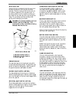
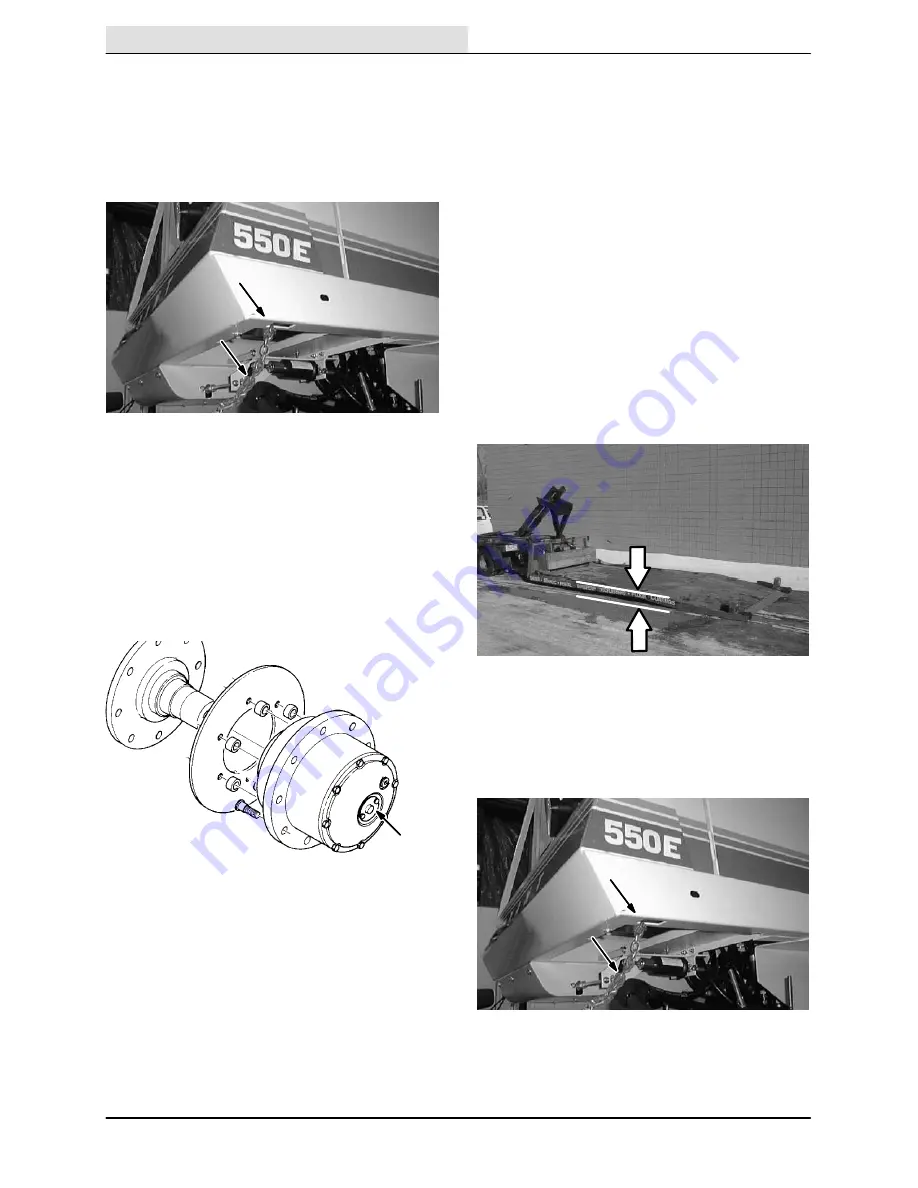
If the machine becomes disabled, it can be towed
from the front tie down holes or from the rear
bumper mounts.
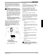
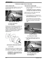
A
B
FRONT TOWING LOCATION
A. Front Tie Down Holes
B. Towing Chain
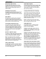
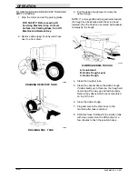
This machine is not designed to be pushed. The
propelling system can be disengaged to prevent
damage to the propelling system when the
machine is being towed. Remove the cover plates
from the front drive wheels before towing the
machine. This will disengage the electric
propelling motors.
A
DISENGAGING PROPELLING MOTORS
A. Cover Plate
Only tow the machine for a short distance and do
not exceed 3.2 kp/h (2 mph). It is NOT intended
to be towed for a long distance or at a high speed.
ATTENTION! Do not tow machine for a
long distance or damage may occur to
the propelling system.
TRANSPORTING THE MACHINE
1. Position the machine at the loading edge of
the truck or trailer.
FOR SAFETY: Use truck or trailer that
will support the weight of the machine.
NOTE: Empty the recovery and solution tanks
before transporting the machine.
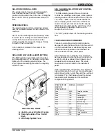
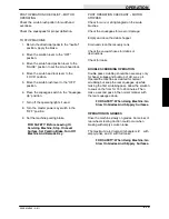
2. If the loading surface is not horizontal or is
higher than 380 mm (15 in) from the ground,
use a winch to load machine.
If the loading surface is horizontal AND is
380 mm (15 in) or less from the ground, the
machine may be driven onto the truck or
trailer.
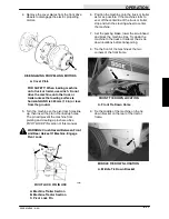
LOADING SURFACE
A. Loading Surface Height
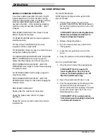
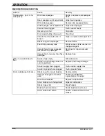
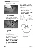
3. To winch the machine onto the truck or
trailer, attach the winching chains to the
machine.
A
B
ATTACHING WINCHING CHAINS
A. Front Tie Down Holes
B. Winching Chain
Содержание 550
Страница 10: ...GENERAL INFORMATION 550E MM149 3 94 viii ...
Страница 12: ...OPERATION 550E MM149 3 91 2 2 ...
Страница 30: ...OPERATION 550E MM149 9 00 2 20 ...
Страница 32: ...MAINTENANCE 550E MM149 3 91 3 2 ...
Страница 62: ...MAINTENANCE 550E MM149 2 05 3 32 ...
Страница 66: ...APPENDIX 550E MM149 3 91 4 4 ...
Страница 74: ...STANDARD PARTS 550E MM149 5 01 6 4 Fig 2 Replacement Brushes 1 ...
Страница 96: ...STANDARD PARTS 550E MM149 5 01 6 26 Fig 17 Electric Motor Group 1 2 3 4 5 6 ...
Страница 105: ...STANDARD PARTS 6 35 550E MM149 5 01 Fig 23 Electrical Schematic 1 2 3 4 5 01228 550E ...
Страница 106: ...STANDARD PARTS 550E MM149 5 01 6 36 Fig 23 Electrical Schematic 1 2 3 4 5 01228 550E ...
Страница 108: ...STANDARD PARTS 550E MM149 5 01 6 38 Fig 24 Power Wheel Group 2 3 4 5 6 1 5 Hydraulic Brake Assembly ...
Страница 110: ...STANDARD PARTS 550E MM149 5 01 6 40 Fig 25 Electrical Wire Harness Group 1 2 3 4 5 6 7 8 9 10 11 12 13 ...
Страница 117: ...STANDARD PARTS 6 47 550E MM149 5 01 Fig 31 Hydraulic Schematic 001330 005607 02361 550E ...
Страница 118: ...STANDARD PARTS 550E MM149 5 01 6 48 Fig 32 Hydraulic Schematic 005608 11118 550E ...
Страница 168: ...OPTIONS 550E MM149 9 99 8 18 ...
Страница 182: ...BREAKDOWNS 550E MM149 10 10 9 14 ...
Страница 196: ...CROSS REFERENCE 550E MM149 10 10 10 14 ...

