OPERATION
2-17
550E MM149 (9--00)
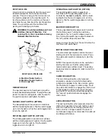
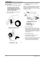
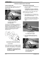
4. Remove the cover plates from the front drive
wheels to disengage the electric propelling
motors.
A
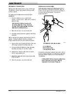
DISENGAGING PROPELLING MOTORS
A. Cover Plate
FOR SAFETY: When loading machine
onto truck or trailer, use winch. Do not
drive the machine onto the truck or
trailer unless the loading surface is
horizontal AND is 380 mm (15 in) or less
from the ground.
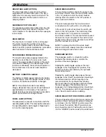
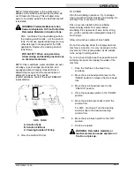
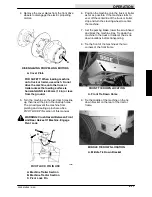
5. Turn the machine so the pivot lock holes line
up, then insert the pin in the lined up holes.
The pin will prevent the machine from
pivoting and creating a pinch area.See
PIVOT LOCK PIN
section of this manual.
WARNING: Crush Hazard Between Front
And Rear Halves Of Machine. Engage
Pivot Lock.
B
C
A
00251
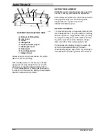
PIVOT LOCK PIN IN USE
A. Machine Trailer Section
B. Machine Tractor Section
C. Pivot Lock Pin
6. Position the machine onto the truck or trailer
as far as possible. If the machine starts to
veer off the centerline of the truck or trailer,
stop and turn the steering wheel to center
the machine.
7. Set the parking brake, lower the scrub head
and block the machine tires. Tie down the
machine to the truck or trailer at the six tie
down locations before transporting.
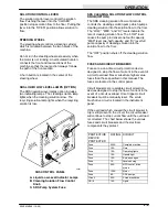
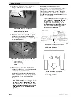
8. Tie the front of the machine at the two
corners of the front frame.
A
FRONT TIE DOWN LOCATION
A. Front Tie Down Holes
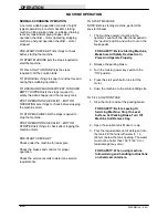
9. Tie the middle of the machine on the tie
down bracket on the rear of the tractor
frame.
A
MIDDLE TIE DOWN LOCATION
A. Middle Tie Down Bracket
Содержание 550
Страница 10: ...GENERAL INFORMATION 550E MM149 3 94 viii ...
Страница 12: ...OPERATION 550E MM149 3 91 2 2 ...
Страница 30: ...OPERATION 550E MM149 9 00 2 20 ...
Страница 32: ...MAINTENANCE 550E MM149 3 91 3 2 ...
Страница 62: ...MAINTENANCE 550E MM149 2 05 3 32 ...
Страница 66: ...APPENDIX 550E MM149 3 91 4 4 ...
Страница 74: ...STANDARD PARTS 550E MM149 5 01 6 4 Fig 2 Replacement Brushes 1 ...
Страница 96: ...STANDARD PARTS 550E MM149 5 01 6 26 Fig 17 Electric Motor Group 1 2 3 4 5 6 ...
Страница 105: ...STANDARD PARTS 6 35 550E MM149 5 01 Fig 23 Electrical Schematic 1 2 3 4 5 01228 550E ...
Страница 106: ...STANDARD PARTS 550E MM149 5 01 6 36 Fig 23 Electrical Schematic 1 2 3 4 5 01228 550E ...
Страница 108: ...STANDARD PARTS 550E MM149 5 01 6 38 Fig 24 Power Wheel Group 2 3 4 5 6 1 5 Hydraulic Brake Assembly ...
Страница 110: ...STANDARD PARTS 550E MM149 5 01 6 40 Fig 25 Electrical Wire Harness Group 1 2 3 4 5 6 7 8 9 10 11 12 13 ...
Страница 117: ...STANDARD PARTS 6 47 550E MM149 5 01 Fig 31 Hydraulic Schematic 001330 005607 02361 550E ...
Страница 118: ...STANDARD PARTS 550E MM149 5 01 6 48 Fig 32 Hydraulic Schematic 005608 11118 550E ...
Страница 168: ...OPTIONS 550E MM149 9 99 8 18 ...
Страница 182: ...BREAKDOWNS 550E MM149 10 10 9 14 ...
Страница 196: ...CROSS REFERENCE 550E MM149 10 10 10 14 ...

