MAINTENANCE
550E MM149 (12--05)
3-22
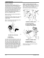
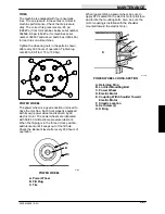
SRS SOLUTION TANK
The tank has a capacity of 265 gal (1000 L).
When the tank is full, a ball float will rise and shut
off the vacuum to the tank. A 72 in (1830 mm)
long drain hose for the recovery tank is located on
the front of the tank. You can determine the water
level in the tank by lowering the hose end until
water appears--this will then be the water level in
the tank (motor must be be off; this stops
vacuum). To drain the tank, lower the hose and
place near a suitable floor drain.
Empty and clean the solution tank and flush the
laminar tubes daily.
Partially fill the solution tank with clean water. Run
the SRS pump for a few minutes to flush the
solution hoses.
NOTE: The water must not be hotter than 130
_
F
(54
_
C) or tank damage may occur.
00343
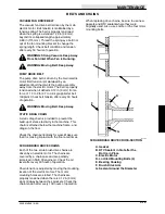
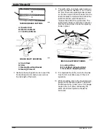
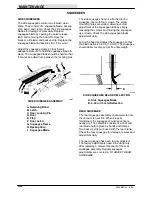
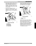
DRAINING SOLUTION TANK
A. Drain Hose
B. Clean out Door
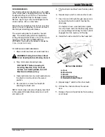
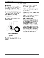
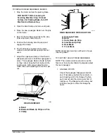
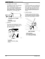
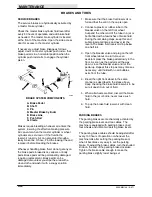
Six clean-out doors are provided on the tank, two
at the front, two at the upper rear, and two at the
lower rear of the tank. Using the sludge removal
tool, remove all sand, sludge, debris, etc., from
the tank. Remove the two large plugs above the
tank tires near the upper front of the tank. Flush
the sediment from all compartments of the tank,
and the wire mesh filters. Check for dirt buildup in
the laminar flow tubes. To clean tubes, remove
and flush. Also, check the return hoses and
connections for clogging or damage.
NOTE: For machines below serial number
004934, when replacing the clean-out doors, the
thumbscrews should be tightened to 20 -- 50 in lb
(2.26 -- 5.65 Nm). Do not over-tighten. Too much
torque on the thumbscrews will cause the
clean-out doors to bow and cut the door seals.
A
C
B
00345
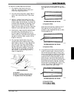
REMOVING LAMINAR TUBES
A. Solution Outlet Filter
B. Laminar Tube Set Fastener
C. Upper Rear Clean-Out Door
A
B
00342
REMOVING LAMINAR TUBES
A. Laminar Tube Set
B. Upper Rear Clean-Out Door
NOTE: Keep laminar tube sections facing the
outside of the machine.
Содержание 550
Страница 10: ...GENERAL INFORMATION 550E MM149 3 94 viii ...
Страница 12: ...OPERATION 550E MM149 3 91 2 2 ...
Страница 30: ...OPERATION 550E MM149 9 00 2 20 ...
Страница 32: ...MAINTENANCE 550E MM149 3 91 3 2 ...
Страница 62: ...MAINTENANCE 550E MM149 2 05 3 32 ...
Страница 66: ...APPENDIX 550E MM149 3 91 4 4 ...
Страница 74: ...STANDARD PARTS 550E MM149 5 01 6 4 Fig 2 Replacement Brushes 1 ...
Страница 96: ...STANDARD PARTS 550E MM149 5 01 6 26 Fig 17 Electric Motor Group 1 2 3 4 5 6 ...
Страница 105: ...STANDARD PARTS 6 35 550E MM149 5 01 Fig 23 Electrical Schematic 1 2 3 4 5 01228 550E ...
Страница 106: ...STANDARD PARTS 550E MM149 5 01 6 36 Fig 23 Electrical Schematic 1 2 3 4 5 01228 550E ...
Страница 108: ...STANDARD PARTS 550E MM149 5 01 6 38 Fig 24 Power Wheel Group 2 3 4 5 6 1 5 Hydraulic Brake Assembly ...
Страница 110: ...STANDARD PARTS 550E MM149 5 01 6 40 Fig 25 Electrical Wire Harness Group 1 2 3 4 5 6 7 8 9 10 11 12 13 ...
Страница 117: ...STANDARD PARTS 6 47 550E MM149 5 01 Fig 31 Hydraulic Schematic 001330 005607 02361 550E ...
Страница 118: ...STANDARD PARTS 550E MM149 5 01 6 48 Fig 32 Hydraulic Schematic 005608 11118 550E ...
Страница 168: ...OPTIONS 550E MM149 9 99 8 18 ...
Страница 182: ...BREAKDOWNS 550E MM149 10 10 9 14 ...
Страница 196: ...CROSS REFERENCE 550E MM149 10 10 10 14 ...

