MAINTENANCE
3-17
550E MM149 (6--96)
TO ADJUST SCRUB BRUSH PATTERN
1. The machine must have correct tire
pressures, full solution tank, and correct
scrub head height adjustment.
2. On a smooth, level surface, apply chalk or
some other material that won’t blow away
easily.
3. With the scrubber head raised, move the
machine over the test area. Start the brush
rotation, apply the foot brakes, and lower the
scrubber head, allowing the brushes to spin
in one spot for 15 to 20 seconds. With no
chalk or other material on the floor, allow the
brushes to spin approximately two minutes.
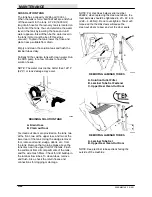
4. Polish marks made by both brushes should
be visible. They should be about 1.5 in
(40 mm) wide the full length of the brush.
With a soft brush, the polish mark should not
exceed 2 in (50 mm) wide, evenly, the full
length of the brush.
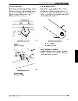
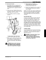
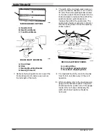
5. The rear brush polish mark is the most
critical and should be adjusted first. If the
polish mark is uneven or cone shaped from
one end to the other, the brush leveling
spring, located at the operator side of the
head lift, should be adjusted. The spring
compensates for the weight of the brush
drive motors. Loosen the top nut first to
make the adjustment.
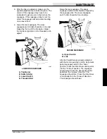
B
C
A
00285
LEVELING BRUSH
A. Top Nut
B. Brush Levelling Adjusting Nut
C. Operator Side of Scrub Head
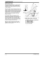
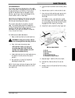
Lower the brush leveling adjustment nut if
the polish mark is too wide on the operator’s
side.
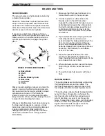
A
00082
TAPERED BRUSH PATTERN
A. Operator Side
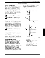
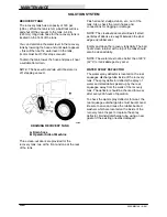
Raise the brush leveling adjustment nut if
the polish mark is too narrow on the
operator’s side. Retighten the top nut after
making adjustments.
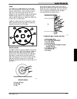
A
00082
TAPERED BRUSH PATTERN
A. Operator Side
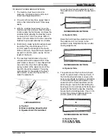
6. The polish mark of the front brush should
match the polish mark of the rear brush. If
the front brush polish mark is uneven, the
narrow side should be shimmed. Add shims
to the shaft bearing mount located on the
underside of the scrub head. Remove the
debris trough, loosen the bolts holding the
bearing protector, and loosen the flat socket
head bolts that hold the bearing mounting
bracket before installing shims. One 0.12 in
(3 mm) thick shim will add about 0.50 in
(13 mm) width to the polish mark.
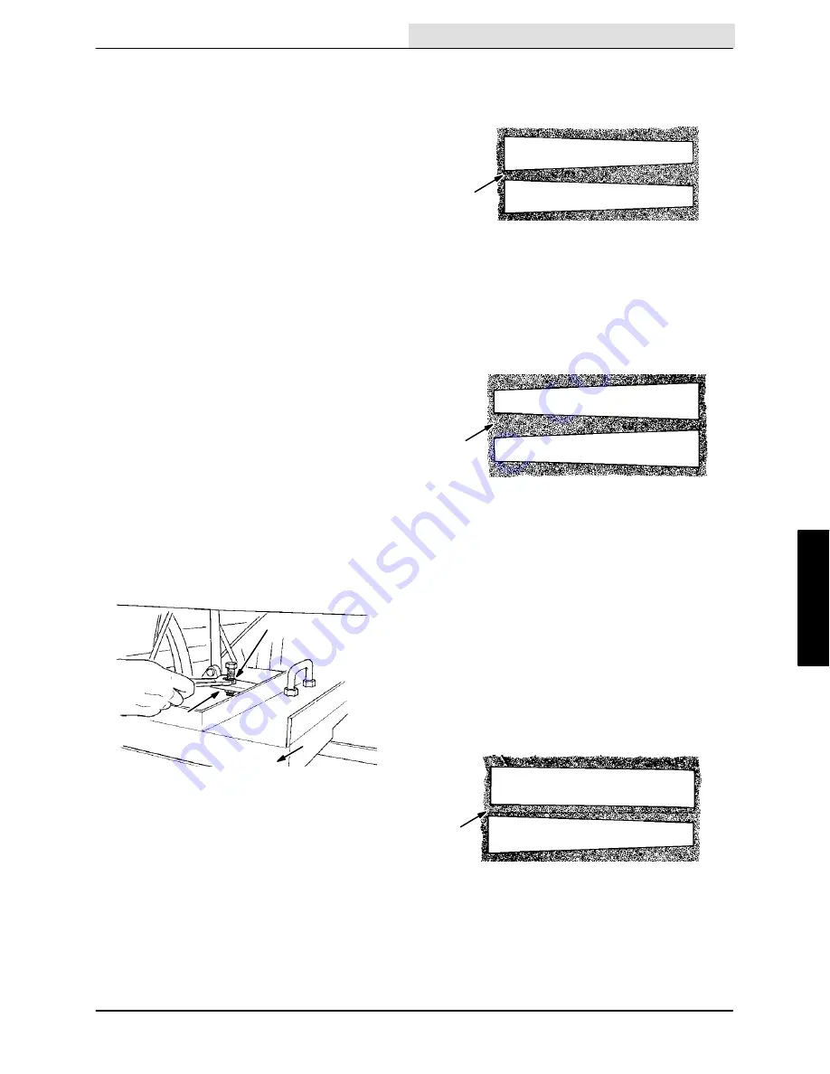
B
A
C
00082
TAPERED BRUSH PATTERN
A. Operator Side
B. Rear Brush Marks
C. Front Brush Marks
Содержание 550
Страница 10: ...GENERAL INFORMATION 550E MM149 3 94 viii ...
Страница 12: ...OPERATION 550E MM149 3 91 2 2 ...
Страница 30: ...OPERATION 550E MM149 9 00 2 20 ...
Страница 32: ...MAINTENANCE 550E MM149 3 91 3 2 ...
Страница 62: ...MAINTENANCE 550E MM149 2 05 3 32 ...
Страница 66: ...APPENDIX 550E MM149 3 91 4 4 ...
Страница 74: ...STANDARD PARTS 550E MM149 5 01 6 4 Fig 2 Replacement Brushes 1 ...
Страница 96: ...STANDARD PARTS 550E MM149 5 01 6 26 Fig 17 Electric Motor Group 1 2 3 4 5 6 ...
Страница 105: ...STANDARD PARTS 6 35 550E MM149 5 01 Fig 23 Electrical Schematic 1 2 3 4 5 01228 550E ...
Страница 106: ...STANDARD PARTS 550E MM149 5 01 6 36 Fig 23 Electrical Schematic 1 2 3 4 5 01228 550E ...
Страница 108: ...STANDARD PARTS 550E MM149 5 01 6 38 Fig 24 Power Wheel Group 2 3 4 5 6 1 5 Hydraulic Brake Assembly ...
Страница 110: ...STANDARD PARTS 550E MM149 5 01 6 40 Fig 25 Electrical Wire Harness Group 1 2 3 4 5 6 7 8 9 10 11 12 13 ...
Страница 117: ...STANDARD PARTS 6 47 550E MM149 5 01 Fig 31 Hydraulic Schematic 001330 005607 02361 550E ...
Страница 118: ...STANDARD PARTS 550E MM149 5 01 6 48 Fig 32 Hydraulic Schematic 005608 11118 550E ...
Страница 168: ...OPTIONS 550E MM149 9 99 8 18 ...
Страница 182: ...BREAKDOWNS 550E MM149 10 10 9 14 ...
Страница 196: ...CROSS REFERENCE 550E MM149 10 10 10 14 ...

