OPERATION
2-15
550E MM149 (2--05)
OPTION OPERATION
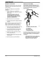
VACUUM WAND
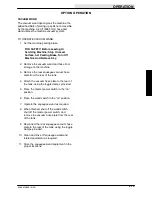
The vacuum wand option gives the machine the
added flexibility of picking up spills not accessible
by the machine. A 20 ft (6095 mm) hose and
wand utilizes the machine vacuum system.
TO OPERATE VACUUM WAND:
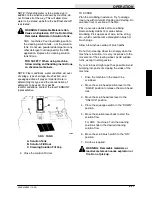
1. Set the machine parking brake.
FOR SAFETY: Before Leaving Or
Servicing Machine; Stop On Level
Surface, Set Parking Brake, Turn Off
Machine And Remove Key.
2. Remove the vacuum wand and hose from
storage on the machine.
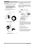
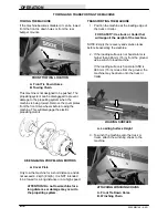
3. Remove the rear squeegee vacuum hose
plate from the rear of the tank.
4. Attach the vacuum hose plate to the rear of
the tank, using the toggle clamps provided.
5. Place the master power switch in the “on”
position.
6. Place the wand switch in the “on” position.
7. Operate the squeegee wand as required.
8. When finished, shut off the wand switch,
shut off the master power switch, and
remove the vacuum hose plate from the rear
of the tank.
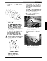
9. Reconnect the rear squeegee vacuum hose
plate to the rear of the tank, using the toggle
clamps provided.
10. Clean and rinse off squeegee wand and
related equipment as required.
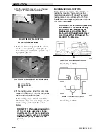
11. Store the squeegee wand equipment in the
proper locations.
Содержание 550
Страница 10: ...GENERAL INFORMATION 550E MM149 3 94 viii ...
Страница 12: ...OPERATION 550E MM149 3 91 2 2 ...
Страница 30: ...OPERATION 550E MM149 9 00 2 20 ...
Страница 32: ...MAINTENANCE 550E MM149 3 91 3 2 ...
Страница 62: ...MAINTENANCE 550E MM149 2 05 3 32 ...
Страница 66: ...APPENDIX 550E MM149 3 91 4 4 ...
Страница 74: ...STANDARD PARTS 550E MM149 5 01 6 4 Fig 2 Replacement Brushes 1 ...
Страница 96: ...STANDARD PARTS 550E MM149 5 01 6 26 Fig 17 Electric Motor Group 1 2 3 4 5 6 ...
Страница 105: ...STANDARD PARTS 6 35 550E MM149 5 01 Fig 23 Electrical Schematic 1 2 3 4 5 01228 550E ...
Страница 106: ...STANDARD PARTS 550E MM149 5 01 6 36 Fig 23 Electrical Schematic 1 2 3 4 5 01228 550E ...
Страница 108: ...STANDARD PARTS 550E MM149 5 01 6 38 Fig 24 Power Wheel Group 2 3 4 5 6 1 5 Hydraulic Brake Assembly ...
Страница 110: ...STANDARD PARTS 550E MM149 5 01 6 40 Fig 25 Electrical Wire Harness Group 1 2 3 4 5 6 7 8 9 10 11 12 13 ...
Страница 117: ...STANDARD PARTS 6 47 550E MM149 5 01 Fig 31 Hydraulic Schematic 001330 005607 02361 550E ...
Страница 118: ...STANDARD PARTS 550E MM149 5 01 6 48 Fig 32 Hydraulic Schematic 005608 11118 550E ...
Страница 168: ...OPTIONS 550E MM149 9 99 8 18 ...
Страница 182: ...BREAKDOWNS 550E MM149 10 10 9 14 ...
Страница 196: ...CROSS REFERENCE 550E MM149 10 10 10 14 ...


