AZ
2
USER MANUAL
ST.TEC.003.EN Rev. 2.1
29 / 52
6.
OPERATION OF TWO SYNCHRONIZED MOTORS
!
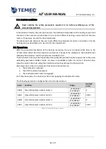
Read carefully the safety precautions reported in 1.5 before operating the drive!
In this operation mode, the drive can control the movement of two motors trying to move them in
synchronous, basing on the encoders signals. The applied voltage follows the desired ramp set by the
user but at the same time the drive increases or decreases the voltages depending on the position
error.
The user can set two electronic limit positions thanks to the encoder’s signals but the drive can also
work with two mechanical limit switches.
The movement stops when the relative limit signal goes high (electronic or mechanic), when a
current limit is achieved, when the command is released or the STOP signal goes high.
All the parameters are set independently for both motors and for the opening and closing movement.
When the drive is not applying voltage to the motor, the terminals are short-circuited to ground.
6.1.
Connections and commands
!
Read carefully the safety precautions reported in 1.4 before wiring the drive!
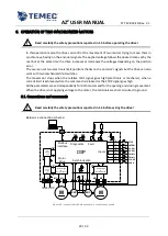
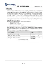
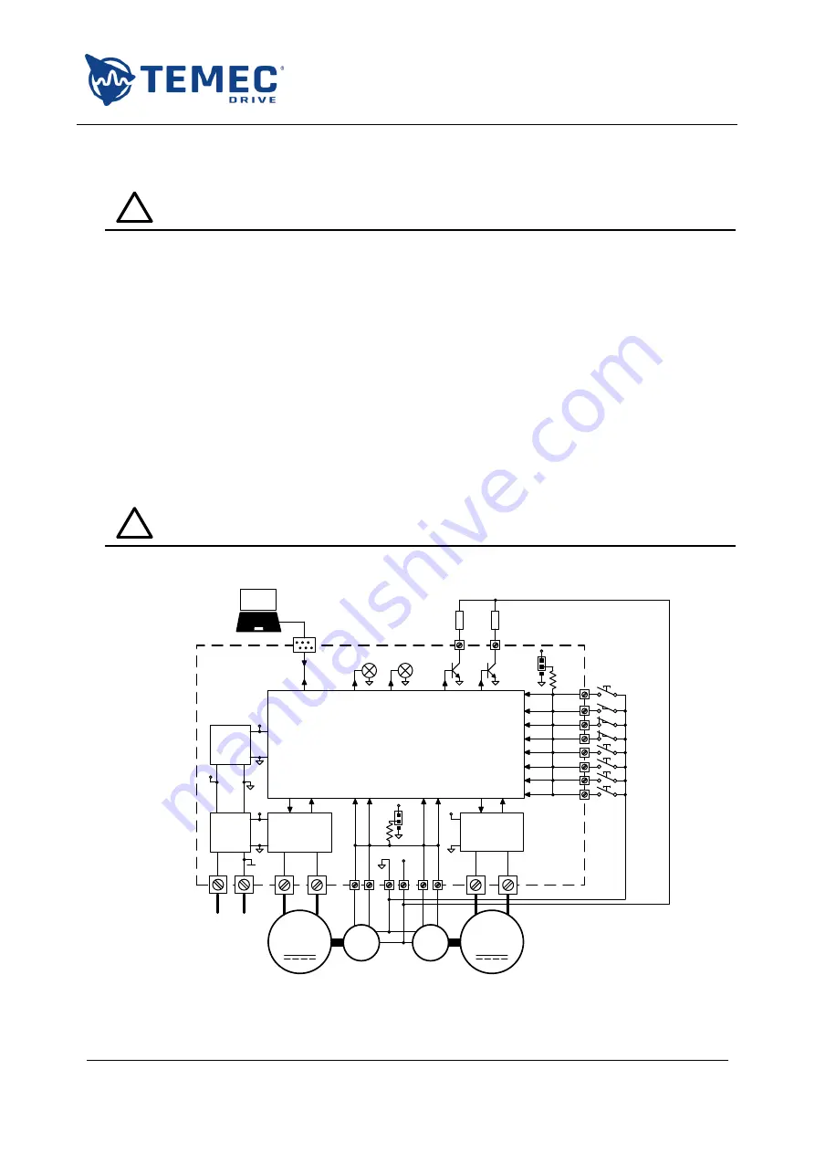
Below is a connection scheme:
M
ENC
Power stage
&
Current sense
M
ENC
Power stage
&
Current sense
Switching
power
supply
12 V
DC
regulator
3.3 V
1
0
k
Ω
+V
+
3.3V
12V
12V
DSP
1
0
k
Ω
+
12V
12-48V DC
RED
RGB
Modbus
interface
Inputs
Diagnostics
Synchronization
Motor
Drive
M1+
M1-
M2+
M2-
1
2
3
4
5
6
7
8
11 12
9 10
15 16
0V
13
14
J1
J2
12V
OPEN
CLOSE
TRIM-1
TRIM-2
OP-SW
CL-SW
INT-SW
STOP
Fault
Figure 16: connection scheme example in synchronous mode
Содержание AZ2
Страница 1: ...AZ2 DC MOTOR DRIVE USER MANUAL ...


