AZ
2
USER MANUAL
ST.TEC.003.EN Rev. 2.1
18 / 52
4.2.
Ramps
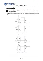
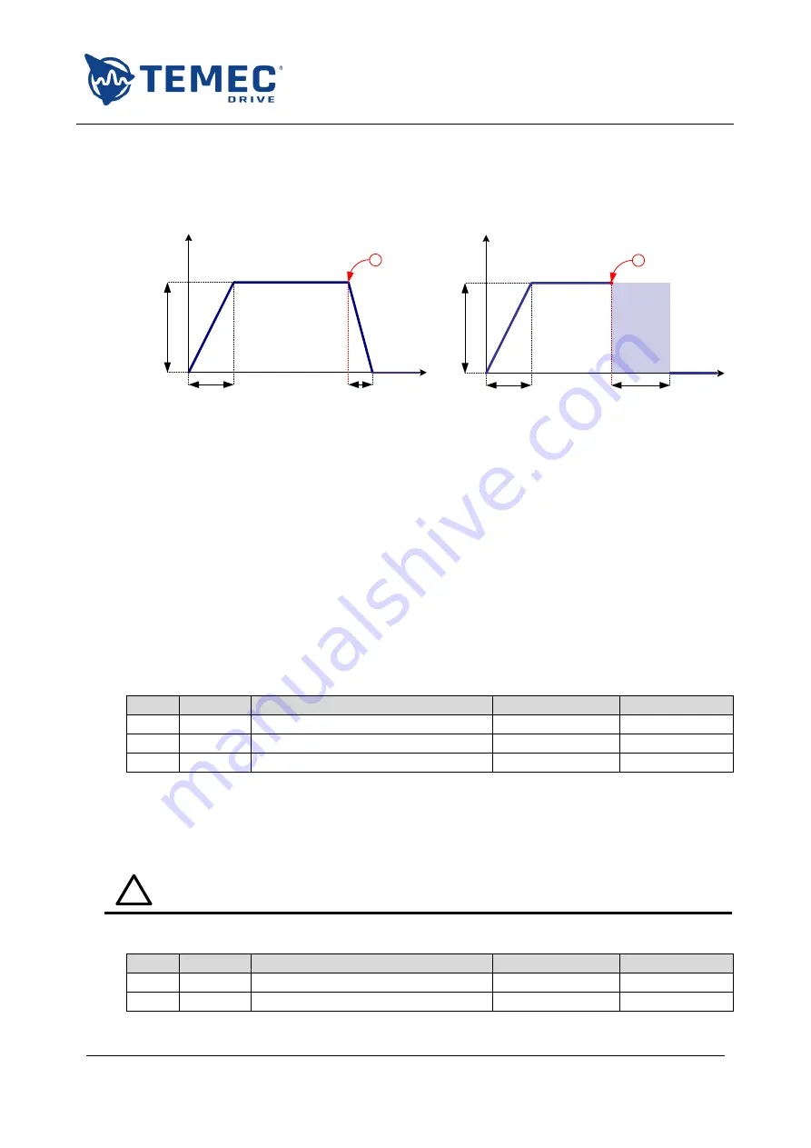
The following figures show how the drive applies the voltage to the motors. The example is the
acceleration and deceleration ramp for motor 1 during the opening movement with two different
stops:
V
t
V
t
M101
M102
M100
!
!
High
impedance
M101
M106
M100
Figure 8: ramp waveform example in case of normal stop (left) and overcurrent (right)
In both cases the full voltage is applied gradually, following a ramp long
M101
ms.
In the first case (Figure 8 - left) the motor stops because the drive reduces the voltage until 0 V, in
M102
ms. Excluding errors, this happens if:
the command is released;
the STOP command is pressed;
the limit switch is engaged.
When an overcurrent is detected the drive behaviour follows Figure 8 - right: the motor terminals
are disconnected from the power stage (no voltage applied) for
M106
= 500 ms and the stop is
achieved by inertia.
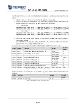
The ramps applied to the motors are set using three parameters (see 8.2 for the complete list):
Label
Output
Function
Range
Default value
M100
Motor 1
Open voltage
10 – 48 [V]
24
M101
Motor 1
Open acceleration ramp
100 – 3000 [ms]
500
M102
Motor 1
Open deceleration ramp
100 – 3000 [ms]
500
Table 9: example of ramp parameters
The user can set different ramps for the two motor and for each direction.
4.2.1.
A
DVANCED PARAMETERS
!
Read carefully the safety precautions reported in 1.6 before modifying any of the
advanced parameters!
In advanced mode the user can modify this further parameters:
Label
Output
Function
Range
Default value
M106
Motor 1
Motor 1 inertial braking time
500 – 3000 [ms]
500
M206
Motor 2
Motor 2 inertial braking time
500 – 3000 [ms]
500
Содержание AZ2
Страница 1: ...AZ2 DC MOTOR DRIVE USER MANUAL ...


