S
TEP
10:
M
OUNT AND CONNECT THE
P
OWER
/E
NABLE
S
WITCH
(
ES
)
P
OWER
/E
NABLE
C
IRCUITS
(P14)
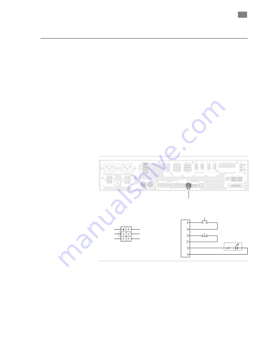
The eF-785’s power controls provide a means with which to turn on and
off machine power as well as a visual indication that the machine is
powered (via the pilot lamp). The On/Enable switch also allows the
operator to reset the eF-785 after an E-Stop event has occurred (when
the post E-Stop Enable feature is enabled).
Note: Your machine’s On-Off
switch and pilot lamp should be mounted in an area that is both
viewable by and readily accessible to the operator.
The machine’s On/Enable switch requires only a momentary normally
open (NO) switch, and, if equipped with an integrated 24VDC pilot lamp
or LED, makes the use of a separate machine “on” pilot lamp
unnecessary. Similarly, the machine’s “off” switch should be a
momentary, normally closed (NC) switch.
The pilot lamp circuit in the eF-785 can be used with incandescent
lamps that consume 1 Watt or less. All voltages within this circuit are low
voltage and are “touch safe”.
115V
JA Host Power
JB Host Power
P3
Main
AC Motor Power
Load
AC Motor Power
J4
SA
F1, F2 Host Pwr. 8A Max
P12
Safety Harness
Hazardous
AC Out
J2
P14
P13
Safety Control Ext.
DC Motor Supply
48-90VDC
24VDC
Supplies
J5
P6
USB
P15
P16
Main DC Motor Pwr.
90VDC Max.
P7A
P7B
P18
40V
100-125/200-240
VAC~ 20A, 50-60Hz
P9 A,B
24VDC
Ckt. 1
P10 A,B
24VDC
Ckt. 2
J8A
J8B
Option DC Motor Pwr.
90VDC Max.
P11 A,B
24VDC
Ckt. 3
Net Out
Net In
RED
BLK
P2
IEEE-1284 Host Port
J17
POWER/ENABLE
SWITCH CONNECTOR
(P14)
4. On-B
1. On-A
2. Off-A
3. Pilot -
5. Off-B
6. Pilot +
P14
On-A
On-B
Off-A
Off-B
Pilot +
Pilot -
1
4
5
2
P14
6
3
On/Enable
Off
Pilot
P14 Connector and Typical Power/Enable switch
schematic
An alternative to having separate On and Off switches is to use a
combination rotary switch that combines the On/Reset switch, Off
switch, and pilot lamp. Using a combination switch such as this not only
allows you to provide front panel controls using only one component, but
also the front panel wiring harness from P14 on the eF-785 to this switch
can be wired with one straight point-to-point cable. Teknic recommends
a 22 mm rotary switch such as the Omron/A22W-3AG-24A-11.
e F - 7 8 5
I
N S T A L L A T I O N
M
A N U A L
43
T
EKNIC
,
I
NC
F
AX
(585)784-7460
V
OICE
(585)784-7454
Содержание EF-785
Страница 2: ...THIS PAGE INTENTIONALLY LEFT BLANK ...
Страница 66: ...APPENDIX C CABLE DIAGRAMS 48 90VDC LOAD AREA TO SST J8A J8B 64 VERSION 1 42 AUGUST 26 2005 ...
Страница 67: ...48 90VDC MAIN AREA TO SST P7A P7B eF 785 INSTALLATION MANUAL 65 TEKNIC INC FAX 585 784 7460 VOICE 585 784 7454 ...
Страница 68: ...48 90VDC LOAD AREA TO ISC J8A J8B 66 VERSION 1 42 AUGUST 26 2005 ...
Страница 70: ...AC SERVO POWER CABLE LOAD AREA J4 68 VERSION 1 42 AUGUST 26 2005 ...
Страница 71: ...AC SERVO POWER CABLE MAIN AREA P3 eF 785 INSTALLATION MANUAL 69 TEKNIC INC FAX 585 784 7460 VOICE 585 784 7454 ...
Страница 72: ...SST 6000 3000 DC POWER JUMPER CABLE 70 VERSION 1 42 AUGUST 26 2005 ...
Страница 73: ...SST 6000 3000 AC INPUT CABLE eF 785 INSTALLATION MANUAL 71 TEKNIC INC FAX 585 784 7460 VOICE 585 784 7454 ...
Страница 74: ...SINGLE 24VDC SUPPLY CABLE J5 72 VERSION 1 42 AUGUST 26 2005 ...
Страница 75: ...DUAL 24VDC SUPPLY CABLE J5 eF 785 INSTALLATION MANUAL 73 TEKNIC INC FAX 585 784 7460 VOICE 585 784 7454 ...
Страница 76: ...70 90VDC SUPPLY CABLE SST EMF75 P6 74 VERSION 1 42 AUGUST 26 2005 ...
Страница 77: ...24VDC DIST CABLE IOC APC P9 P11 eF 785 INSTALLATION MANUAL 75 TEKNIC INC FAX 585 784 7460 VOICE 585 784 7454 ...
Страница 78: ...40VDC POWER TAP DISTRIBUTION CABLE P18 76 VERSION 1 42 AUGUST 26 2005 ...
Страница 80: ...INTEGRATION TESTING CHEATER PLUG SAFETY CONTROL CKTS P12 78 VERSION 1 42 AUGUST 26 2005 ...
Страница 81: ...EXTENSION CHEATER PLUG P13 eF 785 INSTALLATION MANUAL 79 TEKNIC INC FAX 585 784 7460 VOICE 585 784 7454 ...
Страница 82: ...INPUT POWER CABLE J2 80 VERSION 1 42 AUGUST 26 2005 ...


