4. INSTALLATION PROCEDURE FOR OPTIONAL EQUIPMENT
EO18-33012A
4.6 USB INTERFACE BOARD (B-9700-USB-QM)
4-24
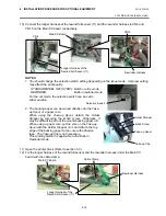
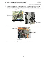
5) If the PCMCIA interface board is used together with the USB interface board, attach the PCB
attachment plate to the plate to which the PCMCIA interface board is secured with the SM-3x6
screw. If not, go to the next step.
6) Firmly connect CN50 connector on the USB interface board directly to CN7 on the Main PC board
or CN1 on the PCMCIA interface board.
When connecting to the Main PC Board:
When connecting the PCMCIA Interface Board:
PCMCIA Interface Board
PCB Attachment Plate SM-3x6 Screw
USB Interface Board
Main PC Board
CN50
CN7
USB Interface Board
PCMCIA Interface Board
CN50
CN1
Содержание B-SX4T Series
Страница 3: ...TEC Thermal Printer B SX4T QQ QP Owner s Manual ...
Страница 54: ......
Страница 56: ......
Страница 57: ......
Страница 58: ...M EO1 33034 ...
Страница 59: ...TEC Thermal Printer B SX5T QQ QP Owner s Manual ...
Страница 105: ...APPENDIX 4 PRINT SAMPLES ENGLISH VERSION EO1 33036 APPENDIX 4 PRINT SAMPLES EA4 1 APPENDIX 4 PRINT SAMPLES n Font ...
Страница 112: ......
Страница 114: ......
Страница 115: ......
Страница 116: ...M EO1 33036 ...
Страница 141: ......
Страница 142: ...PRINTED IN JAPAN EO10 33013A ...
Страница 208: ...5 SYSTEM MODE EO18 33012A 5 4 PARAMETER SETTING 5 19 PC 1250 PC 1251 PC 1252 PC 1253 PC 1254 PC 1257 ...
Страница 312: ......
Страница 313: ......
Страница 314: ...PRINTED IN JAPAN EO18 33012A ...
Страница 315: ......
Страница 316: ...PRINTED IN JAPAN EO0 33013A ...

