4. INSTALLATION PROCEDURE FOR OPTIONAL EQUIPMENT
EO18-33012A
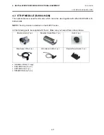
4.3 STRIP MODULE (B-9904-H-QM)
4-16
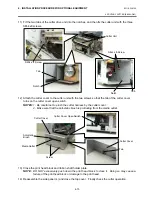
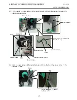
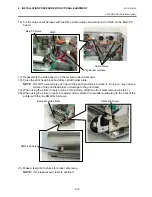
16) Fix the strip sensor harness with the three cable clamps and connect it to CN20 on the Main PC
board.
17) Reassemble the side panel (L) in the reverse order of removal.
18) Close the print head block and ribbon shaft holder plate.
NOTE
: DO NOT excessively push down the print head block to close it. Doing so may cause a
failure of the print head block or damage to the print head.
19) When using the printer in batch mode or strip mode, attach the front plate removed in step 1).
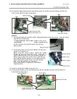
20) When using the printer in built-in rewinder mode, attach the rewinder guide plate to the front of the
printer with the two SMW-4x8 screws.
21) Make a test print to check for proper strip issue.
NOTE:
If the label skews, refer to section 8.
Cable Clamp
CN20
Main PC Board
Strip Sensor Harness
Rewinder Guide Plate
SMW-4x8 Screw
SMW-4x8 Screw
Содержание B-SX4T Series
Страница 3: ...TEC Thermal Printer B SX4T QQ QP Owner s Manual ...
Страница 54: ......
Страница 56: ......
Страница 57: ......
Страница 58: ...M EO1 33034 ...
Страница 59: ...TEC Thermal Printer B SX5T QQ QP Owner s Manual ...
Страница 105: ...APPENDIX 4 PRINT SAMPLES ENGLISH VERSION EO1 33036 APPENDIX 4 PRINT SAMPLES EA4 1 APPENDIX 4 PRINT SAMPLES n Font ...
Страница 112: ......
Страница 114: ......
Страница 115: ......
Страница 116: ...M EO1 33036 ...
Страница 141: ......
Страница 142: ...PRINTED IN JAPAN EO10 33013A ...
Страница 208: ...5 SYSTEM MODE EO18 33012A 5 4 PARAMETER SETTING 5 19 PC 1250 PC 1251 PC 1252 PC 1253 PC 1254 PC 1257 ...
Страница 312: ......
Страница 313: ......
Страница 314: ...PRINTED IN JAPAN EO18 33012A ...
Страница 315: ......
Страница 316: ...PRINTED IN JAPAN EO0 33013A ...


