4. INSTALLATION PROCEDURE FOR OPTIONAL EQUIPMENT
EO18-33012A
4.5 PCMCIA INTERFACE BOARD (B-9700-PCM-QM)
4-22
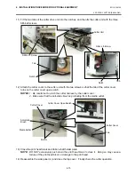
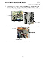
6) Secure the PCMCIA interface board to the PCB support plate with the SM-3x6 screw.
Tighten the two M-3x5 screws that were loosened previously. (Refer to Caution)
7) Attach the blind plate A to the rear plate with the two SM-3x6 screws that were removed in step 6).
If the LAN interface board or USB interface board is also installed, go to the next step.
NOTE
: Keep the two SM-3x6 screws and blind plate A safe when the LAN interface board or USB
interface board is installed.
8) Reassemble the side panel (L) in the reverse order of removal. If the Expansion I/O board was
removed at the beginning, reassemble it.
NOTE
: For inserting, removing, and handling the PC card, refer to the Owner’s Manual.
Blind Plate A
SM-3x6 Screw
Rear Plate
SM-3x6 screw
PCB Support Plate
M-3x5 Screw
Содержание B-SX4T Series
Страница 3: ...TEC Thermal Printer B SX4T QQ QP Owner s Manual ...
Страница 54: ......
Страница 56: ......
Страница 57: ......
Страница 58: ...M EO1 33034 ...
Страница 59: ...TEC Thermal Printer B SX5T QQ QP Owner s Manual ...
Страница 105: ...APPENDIX 4 PRINT SAMPLES ENGLISH VERSION EO1 33036 APPENDIX 4 PRINT SAMPLES EA4 1 APPENDIX 4 PRINT SAMPLES n Font ...
Страница 112: ......
Страница 114: ......
Страница 115: ......
Страница 116: ...M EO1 33036 ...
Страница 141: ......
Страница 142: ...PRINTED IN JAPAN EO10 33013A ...
Страница 208: ...5 SYSTEM MODE EO18 33012A 5 4 PARAMETER SETTING 5 19 PC 1250 PC 1251 PC 1252 PC 1253 PC 1254 PC 1257 ...
Страница 312: ......
Страница 313: ......
Страница 314: ...PRINTED IN JAPAN EO18 33012A ...
Страница 315: ......
Страница 316: ...PRINTED IN JAPAN EO0 33013A ...


