INTRODUCTION
1-15
Models C712/C713
Introduction
1
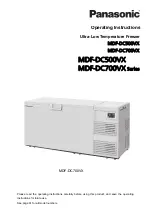
User Interface
C712/C713
Figure 1-3
Note:
*C713 does not have the Mix Pump Button.
3
2
3
6
4
5
11
7
1
8
9
10
5
6
4
Item
Description
1
Power Switch
2
Liquid Crystal Display (LCD)
3
Buttons
4
Mix Out Indicator
5
Standby Button
Item
Description
6
Mix Low Indicator
7
Select Button
8
Service Menu Button
9
Brush Clean Counter
10
Arrow Buttons
11
Wash Button
Содержание C712
Страница 9: ...INTRODUCTION 1 5 Models C712 C713 Introduction 1 Figure 1 1 ...
Страница 11: ...INTRODUCTION 1 7 Models C712 C713 Introduction 1 Figure 1 2 ...
Страница 22: ...1 18 INTRODUCTION Models C712 C713 Introduction 1 Notes ...
Страница 42: ...2 20 CONTROLS Models C712 C713 Controls 2 Control Overview UVC4 Figure 2 58 ...
Страница 48: ...2 26 CONTROLS Models C712 C713 Controls 2 Refrigeration Schematic Figure 2 62 ...
Страница 50: ...2 28 CONTROLS Models C712 C713 Controls 2 Notes ...
Страница 60: ...3 10 TROUBLESHOOTING Models C712 C713 Troubleshooting 3 Notes ...
Страница 91: ...Section 5 5 1 Models C712 C713 Parts List Parts List C71227F000 C71327F000 50HZ 60HZ w High V 50HZ ...
Страница 120: ...6 10 WIRING DIAGRAMS Models C712 C713 Wiring Diagrams 6 Notes ...