Panasonic MDF-C8V1 Series, Operating Instructions Manual
The Panasonic MDF-C8V1 Series comes with an easy-to-follow Operating Instructions Manual, available for free download from manualshive.com. This comprehensive manual ensures that you have all the necessary guidance to optimize your experience with the product, enhancing user convenience and satisfaction.
Share
Download


Reviews:
No comments
Related manuals for MDF-C8V1 Series

ICE
Brand: Lacor Pages: 80

GB 7246
Brand: BOMANN Pages: 52

KG 319
Brand: BOMANN Pages: 32

DSBSDX16
Brand: DeLonghi Pages: 32

ECFR688W
Brand: Euromaid Pages: 28

FFU14FC4CW1
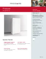
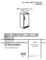
Brand: Frigidaire Pages: 7
FFU14F5H W
Brand: Frigidaire Pages: 2

FFU14C2AW0
Brand: Frigidaire Pages: 2

FFU14FC4CW
Brand: Frigidaire Pages: 7
FFU14F3AW3
Brand: Frigidaire Pages: 7

FFU14C3AW1
Brand: Frigidaire Pages: 7

FFU14C3AW
Brand: Frigidaire Pages: 7

FFU14FC4AW3
Brand: Frigidaire Pages: 7

FFU14F3AW
Brand: Frigidaire Pages: 7

FFU14F9G
Brand: Frigidaire Pages: 8

FFU14FC2CW
Brand: Frigidaire Pages: 7

FFU14F9GW
Brand: Frigidaire Pages: 7

FFU14FC4CW0
Brand: Frigidaire Pages: 7


